FJ = ρ · Q · Δvax Q Flow rate ρ Densityof the fluid handled Δvax Difference between the axial components of the absolute velocity at the impeller inlet and outlet
The resultant pressure forces arising from the static pressures up- and downstream of the shaft seal (ss) on the relevant shaft cross-section Ass: FWd = AWd · ΔpWd
Special axial forces, e.g. when changes to the vortex conditions in the clearances between impeller and casing (side gaps) occur during the start-up process (see Disc friction)
Other axial forces such as the force of the rotor weight (FW) on non-horizontal centrifugal pumps or magnetic pull in theelectric motor(Fmech), e.g. in close-coupled pumps
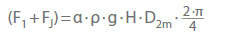
The axial thrust component (F1 + FJ) of closed impellers (i.e. with suction-side shrouds) which are not hydraulically balanced is:
α Axial thrust coefficient (based on experience) ρ Density of fluid handled g Gravitational constant H Head D2m Mean impeller diameter:
The axial thrust coefficient is essentially dependent on the specific speed (ns) For radial and mixed flow impellers the following equation applies in the range of 6 < ns < 130 rpm :
α=0,5 · (Dsp/D2m)3 + 0,09 ≈ 0,1 − 0,3
Dgap seal Diameter of the controlled gap seal at the suction-side impeller shroud
See Fig. 2 Axial thrust
Fig. 2 Axial thrust: Non-balanced impeller design with conical impeller outlet area
This equation applies to flow rates (Q) of 0.8 · Qopt to 1.0 · Qopt and to the clearance gap width s = 0,1 mm. If the clearance gap width is doubled, α increases by 8 %.
the axial impeller force (F1) is largely determined by the impeller's axial position in relation to the diffuser. In the case of open radial impellers with no shrouds on the suction side, the axial force (Fs) is much lower than on closed impellers, meaning that the axial impeller force (F1) is higher.
Open impellers with cut-outs in the impeller shroud between adjoining impeller vanes develop a lower pressure force (Fd), and, consequently, a lower axial force (F1) than impellers with a full discharge side shroud. See Fig. 13Impeller
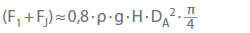
For axial propellers, the axial thrust coefficient (α) is almost equal to the degree of reaction (rth). The axial thrust can then be roughly calculated using the propeller's outside diameter (OD):
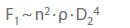
The following proportionality applies to the F1 component of the axial thrust (See Fig.1 Axial thrust) in the case of geometrically similar pumps at a defined rotational speed (n) and at the largest impeller diameter (D2):
The rotation of the fluid handled in the discharge-side and suction-side clearances between impeller and casing exerts a strong influence on the axial pressure forces (Fd) and (Fs). The mean angular velocity (see Rotational speed) of the rotating fluid handled reaches approx. half the impeller speed.
In addition, as a result of Coriolisaccelerations, the inward directed clearance flow in the suction-side (i.e. outer) clearance between impeller and casing (side gap) further increases the side gap turbulences. In the discharge-side (i.e. inner) side gap of multistage pumps whose impellers are not hydraulically balanced, the process is reversed as a result of the outward-directed gap flow. The vortex motion is decelerated resulting in an increase of the axial force Fd, and hence of F1.
The axial impeller force is higher during the start-up process than during steady-state operation, as during start-up rotation of the fluid handled begins slowly due to disc friction caused by the action of the impeller shrouds or the braking effect of the stationary casing surfaces.
Various forms of axial thrust balancing
Mechanical: complete absorption of the axial thrust via a thrust bearing (e. g. plain bearing, rolling element bearing)
Design-based: back-to-back arrangement of the impellers or stages (see Back-to-back impeller pump) and through the absorption of the residual axial thrust via a thrust bearing
Balancing or reduction of the axial thrust on the individual impeller via balancing holesSee Figs. 7, 9 Axial thrust
Balancing of the complete rotating assembly via a balancing device with automatic balancing (e. g. balance disc and balance disc seat) or partial balancing via a balance drum and double drum
Reduction at the individual impeller by back vanes (dynamic effect) See Fig. 8 Axial thrust
Mechanical axial thrust balancing
The absorption of the axial thrust by a rolling element bearing is the most efficient, cost-effective solution. However, if the absence of special balancing equipment requires the use of particularly complex thrust bearings, these benefits in terms of efficiency and costs may be eliminated.
Design-based axial thrust balancing
In the case of an impeller arrangement in a pipeline pump with four stages, each featuring a 2 x 2 back-to-back arrangement, a maximum of twice the normal axial thrust per stage can occur in the event that system conditions cause cavitation in two stages. See Fig. 5 Axial thrust
If, however, a more complex, parallel-coupled back-to-back impeller arrangement is chosen, only the normal axial thrust per stage occurs. See Fig. 6 Axial thrust
Both pump types must be equipped with thrust bearings of appropriate strength.
Fig. 5 Axial thrust: Axial thrust balancing in a four-stage pipeline pump with two opposed sets of two series-coupled impellers each
Fig. 6 Axial thrust: Axial thrust balancing in a four-stage pipeline pump with two sets of parallel-coupled opposed impellers
Axial thrust balancing at the impeller
This is the oldest method for balancing axial thrust and involves reducing the pressure in a chamber equipped with a throttling gap, usually down to the pressure level encountered at the impeller inlet. The pressure is balanced via balancing holes in the impeller.
These balancing holes may lead to variations in axial thrust balancing as a result of varying inlet conditionsSee Fig. 7 Axial thrust
Fig. 7 Axial thrust: Axial thrust balancing in a single-stage centrifugal pump with discharge-side sealing clearance and balancing holes
The angular velocity has a dynamic influence on the magnitude of the axial thrust (see Rotational speed). An increase in angular velocity is mostly achieved by back vanes die which are radially arranged on the rear side of the impeller.
The higher mean angular velocity of the vortices in the clearance between impeller shroud and casing results in a lower static pressure on the discharge-side impeller shroud. This results in a lower axial force Fd and thus a lower F1. See Fig. 8 Axial thrust
Most radial back vanes are designed with diameters (Dbv o, Dbv i), side space depth (a), vane height (h) and vane number (z) which vary according to requirements. The power absorbed by this method of axial thrust balancing depends on the sizing of the back vanes. The pump efficiency may drop by up to three points due to the back vanes. See Fig. 8 Axial thrust
Fig. 8 Axial thrust: Axial thrust balancing in a single-stage centrifugal pump with back vanes
A comparable effect is achieved when the impeller is balanced via the provision of balancing holes at defined areas on the discharge side without fitting a second discharge-side joint ring. The gap flow directed toward the inside creates an angular momentum in the space between the impeller shroud and the casing which increases the local angular velocity and, as a consequence, reduces the static pressure. See Fig. 9 Axial thrust
Fig. 9 Axial thrust: Axial thrust balancing in a single-stage centrifugal pump with balancing holes only
All hydraulic balancing devices are fully effective at optimal flow rate Qopt. Residual forces occurring under low-flow and overload, conditions must be absorbed by thrust bearings. See Figs. 7 to 9 Axial thrust
Axial thrust balancing via balancing devices
Available options
Balance disc with balance disc seat and balancing flowreturn line See Fig. 10 Axial thrust
Balance drum with balancing flow return line and thrust bearing See Fig. 11 Axial thrust
Double drum with balancing fluid return line and thrust bearing See Fig. 12 Axial thrust
In the case of the balance disc, the gap flow (see Clearance gap loss)is low because the self-adjusting axial gap (s) remains very narrow which means that the pump's efficiency is only slightly reduced. However, in the case of the balance drum, the radial clearance gaps are wider and therefore the gap flows are higher, causing a greater drop in efficiency which is then further compounded by the fact that an additional thrust bearing is required. See Fig. 11 Axial thrust
Labyrinth-type gap seals are fitted to minimise the high gap flow (e. g. double drum balancing devices). Thanks to its large axial clearance (s), double drum balancing devices allow an additional thrust bearing to be fitted which is mainly designed to prevent mechanical seizure in the balancing system. See Fig. 12 Axial thrust
Fig. 10 Axial thrust: Balancing device with balance disc
Fig. 11 Axial thrust: Balancing device with balance drum and thrust bearing
Fig. 12 Axial thrust: Balancing device with double drum and thrust bearing
Seizing may occur during start-up, during operation at extreme overloads (see Operating behaviour) or when cavitation takes place. The pump rotor's position and, consequently, the wear of the balancing equipment or thrust bearing can be ascertained by simple devices indicating seizure during operation.
As an international employer, KSB offers exciting challenges in many different areas.
Regardless whether you are an experienced professional or a pupil, student or graduate ─ learn more about our work culture and find job openings from all over the world in our job portal.