Condensate pump
A condensate pump is a centrifugal pump, which is named after the type of fluid handled. It is used in condensers to pump out the condensed steam as water (condensate) in a technical vacuum (near vapour pressure). In an open circuit, the condensate pump transports the condensate into a tank (e.g. feed water tank); in a closed circuit, it pumps the condensate directly into the boiler feed pump via a low-pressure feed heater. See Fig. 1 Condensate pump.

Fig. 1 Condensate pump: Condensate and feed water circuit
The maximum steam mass flow rate of the steam turbine determines the capacity (see Flow rate) of the condensate pump.
Composition of the head:
- Geodetic head difference between the water levels in feed water tank and condenser
- Difference of static pressure heads in feed water tank and condenser
- Head losses of the flow in the pipeline, including installed valves (e. g. gate valve, swing check valve) and system components (e. g. suction strainer, condensate preheater)
The design of the condensate pump is governed by the vapour pressure(opens in a new tab) of the water on the suction side (for pure water at 35 °C approximately 56.2 mbar) and by the low inlet head resulting from the position of the condenser within the structure. The inlet head is calculated by subtracting the flow losses in the inlet line from the geodetic head between the standard water level in the condenser and the level of the impeller of the first stage.
To achieve an optimum operating behaviour and prevent cavitation damage the available NPSH of the system must be greater or equal to the required NPSH at the impeller of the first stage. This applies to the entire operating range.
Measures to increase the system-side inlet head:
- Minimising the flow losses in the inlet line; e. g. by means of larger nominal pipe diameters
- Vertical arrangement, e. g. dry installation, which reduces the height of the first-stage impeller above the installation floor and increases the difference in geodetic head.
See Fig. 2 Condensate pump - Vertical arrangement as a "can-type pump", in which the geodetic head difference is increased by lowering the suction stage into an inlet "can" arranged below the installation floor.
See Fig. 3 Condensate pump
The inlet and discharge lines are arranged above the installation floor.

Fig. 2 Condensate pump: Vertical dry-installed model with double-entry suction stage

Fig. 3 Condensate pump: Vertical "can-type" model with double-entry suction stage
Options of enhancing the suction characteristics of a condensate pump:
- Installing a suction stage impeller
- Installing a inducer
- Installing a double-entry impeller See Figs. 2, 3 Condensate pump
- Reducing the rotational speed
- Enhancing the flow passages in the pump
One design variant is that of a condensate pump with intermediate extraction (re-entry). After the first or second stage of the pump (condensate booster pump with single or double entry suction stage) the entire flow is diverted to the condensate cleaning system. See Fig. 4 Condensate pump

Fig. 4 Condensate pump: Vertical re-entry model; booster pump in inlet "can", main pump arranged above casing with bleed-off and return
The pressure is further increased in the condensate main pump, which is installed above floor, above the booster pump with which it forms a unit.
For flow rates exceeding 150 l/s (540 m3/h) high cavitation loads require particular consideration of the intensity of cavitation, velocity conditions and lengths of the occurring trail of cavitation bubbles. The intensity of cavitation can be measured by means of the material loss rate LM.
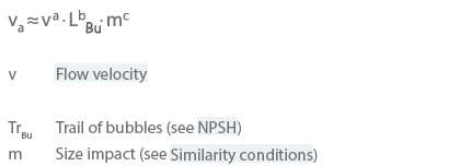
The exponent values depend on the design concept of the suction stage impeller. They lie within the following range:

As the flow velocity at the impeller vane leading edge at a given flow rate cannot be greatly influenced, the lengths of the bubble trails have to be reduced as far as possible.
The shaft seal of condensate pumps must provide sealing against a low technical vacuum during standstill of the pump. This requires the sealing element to be fed with barrier fluid from the system-side barrier system in order to prevent air ingress. In the case of gland packings, a lantern ring is inserted between the packing rings for this purpose. Mechanical seals are designed as inboard and outboard double mechanical seals. The barrier fluid is supplied to either the lantern ring or the chamber between inboard and outboard mechanical seal.
Three-phase motors with squirrel cage are generally used as drives of condensate pumps, if they are suitable for operation with a closed loop control system. The following control options are available to adjust the pump to fluctuating turbine loads and to prevent dry running of the condensate pump.
Options of controlling a condensate pump:
- Adjusting the system characteristic curve by means of throttling with a control valve in the discharge line
- Adjusting the system characteristic curve by returning excess flow to the condenser (bypass adjustment) (see Bypass)
- Adjusting the H/Q curve by altering the pump speed (speed control)
- Adjusting the H/Q curve by letting the flow rate adjust itself to the inlet head (see Suction characteristics). This type of control based on incipient cavitation is also known as "self-regulation". See Fig. 5 Condensate pump
 and NPSHA describing the function of a self-regulating condensate pump (Hz.geoB = geodetic inlet head from condensate tank)")
Fig. 5 Condensate pump: H/Q curves, NPSHR of condensate pump, system characteristic HA(Q) and NPSHA describing the function of a self-regulating condensate pump (Hz.geoB = geodetic inlet head from condensate tank)
The self-regulation of condensate pumps exploits the change in the characteristic curve H(Q) with part of the condensate evaporating upstream of or in the first stage, which reduces the head H(Q) of this stage by a certain amount depending on the extent of blockage by steam (Hcav). Depending on the water level Hz.geo a head breakdown curve (influenced by the extent of cavitation Hcav(Q) is established, whose intersection with the system characteristic Hsys(Q) determines then operating point (OP).
Due to the high cavitation loads, self-regulation of condensate pumps imposes arduous requirements particularly on the first stage of the pump. For this reason this type of regulation is no longer adopted on the larger pumps which are commonly used today.