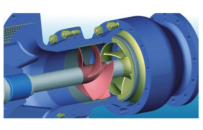
Inducer
An inducer is an axial impeller with a low number of vanes which is arranged immediately upstream of the actual centrifugal pump impeller and rotates at the same rotational speed as the pump impeller. On multistage pumps it is fitted upstream of the first stage.
The inducer's task is to reduce the NPSH required by the pump, which is achieved by increasing the static pressure upstream of the impeller. The vortex flow (pre-swirl in direction of the impeller rotation) downstream of the inducer plays an important role (see Inlet conditions).
See Fig. 1 Inducer

Fig. 1 Inducer: Inducer (illustrated in red) upstream of a submersible borehole pump's first stage
A significant reduction of the required NPSH value using an inducer can only be achieved under low flow conditions. As a result, the operating range of a pump fitted with an inducer is limited when compared with a pump without inducer.
In order to avoid blockage of the flow cross-sections by vapour bubbles (see Cavitation) in the inducer on the vane pressure sides, the inducer should be sized for higher performance than actually required for the desired operating range. It will therefore operate in the low flow range at almost all possible operating points and be able to provide the pump impeller with the required inlet pressure (see Characteristic curve).
Under extreme low flow conditions, low-frequency pressure fluctuations, typical for inducers, can be observed. This is due to cavitation and fluctuating approach flows.
The flow separation on the vane's suction side which may occur under certain circumstances during low flow operation is far less of a problem than flow separation on the vane pressure side, which usually leads to the collapse of the head in the case of axial impellers.
The pump head plays an important part in the evaluation of the efficiency of a pump equipped with an inducer. The inducer operates under conditions of considerable entry shock (see Shock loss in the low flow range) and therefore at a lower efficiency than the pump impeller. The ratio between inducer head and pump impeller head is important as the deterioration of the efficiency of the whole unit, i.e. the inducer and the pump, is highly dependent on this ratio. It follows that the provision of an inducer on pumps with a low specific speed (high head) is less detrimental to efficiency than in the case of high specific speed pumps.
Inducers are mainly available in three different vane designs.
Inducers are mainly available in three different vane designs.
Inducer designs
- Helical surface: the head is solely generated by the vanes'incidence angles (for inducers with a low head).
- Cambered vanes with various types of meridian lines: the head is determined both by incidence and deflection.
- S-curved vanes: these shape the path of the flow deflection (see Vortex flow).
Inducers fitted with a small number of vanes (max. four) have achieved good results in practice as they involve only a small risk of blockage by vapour bubbles. As inducers are exposed to very high stresses as a result of cavitation, they are manufactured using cavitation-resistant materials.
Manufacturing methods frequently used for inducers
- Welding: preformed sheet steel vanes
- NC (numerical control) milling: in accordance with calculated coordinates
- Copy milling: in accordance with an accurate model
- Casting: investment casting method
