Shock loss
If the angle of attack of a vane cascade differs from the inlet angle of the vanes (see Shock-free entry), the loss resulting from the forced change in velocity is called shock loss or impact loss.
It occurs when the flow rate (Q) of a pump is smaller or larger than the value resulting in a shock-free approach flow (Qshock-free) for the respective vane geometry. A change in the flow rate entails a change in the inflow angle and therefore the incidence angle of the vanes.
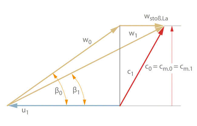
A meridian velocity (cm.0) upstream of the cascade (subscript 0) can be calculated for a given flow rate (Q). The circumferential speed at the impeller inlet (subscript 1) in the flow area is assumed to be u1. Therefore, in the case of a vortex-free approach flow (i.e. c0 = cm. 0), the flow approaches the vane with a relative velocity (w0). It is also assumed that the resulting relative inflow angle is β0 and the vane angle at the impeller inlet is β1. If the flow rate does not equal the flow rate at shock-free entry (Qshock-free), as characterised by the condition β0 = β1, the flow must be abruptly diverted after entering the vane cascade, i.e. from the inflow angle β0 to the angle β1 so that it is able to follow the direction of the vanes.
The meridian velocity in this case remains unchanged (cm.1 = cm.0) (the blocking effect caused by the vanes' thickness shall be ignored). This case is shown in Fig. 1 for an operating point at overload with Q > Qshock-free. See Fig. 1 Shock loss

Fig. 1 Shock loss: Velocity triangles at impeller inlet with shock component wshock.imp vortex-free approach flow
The shock component (wshock.imp) causes a calculated head loss of:

ζshock.imp Shock coefficient for the impeller vane
g Acceleration due to gravity
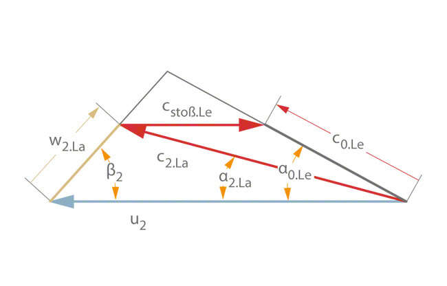
An analogous analysis can be used when evaluating the shock losses in the diffuser. It must be taken into account that, in contrast to the case of vortex-free flow to the impeller inlet, the direction of absolute flow is not independent of the flow rate.
In a first approximation, it can be assumed that the direction of the relative flow (w2.imp) leaving the impeller remains constant within the range 0.75 ∙ Qopt ≤ Q ≤ 1.25 ∙ Qopt.
See Figs. 2, 3 Shock loss
See Figs. 2, 3 Shock loss

Fig. 2 Shock loss: Velocity triangles at impeller outlet (subscript 2.La) and upstream of diffuser inlet (subscript 0.Le ) showing the shock component cshock.Le

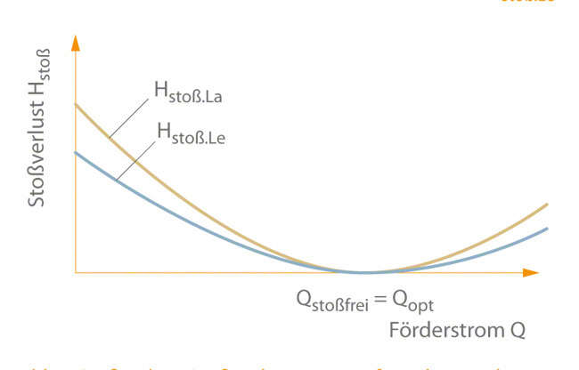
Fig. 3 Shock loss: Shock losses in the impeller and diffuser as a function of flow rate. Qshock-free does not necessarily have the same value for the impeller and the diffuser. Qshock-free may thus differ from Qopt.
When calculating the shock losses, it should be taken into account that the shock coefficient in the low flow range is greater than in the overload range (see Operating behaviour).
This can be explained by the fact that separation occurs under low flow conditions as a result of shock approach flow, particularly in the outer region of the vane cascade, and this separation ultimately results in suction recirculation of the fluid when the shock approach flow becomes extreme.
