Fluid coupling
The fluid coupling consists of a pump impeller (on the input shaft) and a runner (on the output shaft). Both impellers are housed in the same casing. See Fig. 1 Fluid coupling

Fig. 1 Fluid coupling: Schematic of fluid coupling
The pump impeller pushes the fluid inside the casing (usually low-viscosity oil) towards the runner, which causes the output shaft to rotate. Fluid couplings have no diffuser vanes between the pump (index P) and turbine (index T), unlike hydraulic torque converters As there is no diffuser being supported by the static casing, the fluid coupling's input (TP) and output torque (TT) are the same.

The power (PP = T · ωP) and (PT = T · ωT) are used to calculate the efficiency of the fluid coupling.
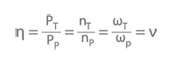
ν Speed ratio between turbine speed and pump speed
ω Angular velocity
ω Angular velocity
When the turbine speed (nT) is equal to zero, the fluid coupling has a very high driving torque. If the turbine speed is equal to the pump speed (nT = nP), the torque (T) equals zero. However, slip always occurs during power transmission, with the result that the turbine speed is lower than that of the pump.
See Fig. 2 Fluid coupling

Fig. 2 Fluid coupling: Characteristic curves for different filling volumes
Using an adjustable scoop tube to change the filling volume (V) makes it possible to control the slip (1-ν) and, in turn, the turbine speed.
In accordance with the hydrodynamic affinity laws, the turbine speed is also dependent on the pump speed. See Fig. 3 Fluid coupling

Fig. 3 Fluid coupling: Characteristic curves for different pump speeds
The wide variety of designs means that the characteristic curves can be matched to the requirements of the driving and the driven machine to the maximum possible extent. See Figs. 4 and 5 Fluid coupling

Fig. 4 Fluid coupling: Characteristic curves for different vane numbers z

Fig. 5 Fluid coupling: Characteristic curves of fluid couplings with a flattened section on the outside diameter and asymmetrical pump impeller and turbine runner
If combined with a gear unit (see gear drive) the fluid coupling is sometimes also referred to as a geared variable speed coupling. Mechanical separation of the input and output shafts dampens torque surges and vibrations. However, the disadvantage is that efficiency is sometimes significantly compromised (e.g. due to fluid coupling temperature rise) as a result of slip. This disadvantage can be mitigated by combining a fluid coupling with a hydraulic torque converter. In the lower speed and power range, the fluid coupling assumes responsibility for operation, whereas in the speed range of 80 to 100 % the input and output shafts are rigidly coupled. This means that the majority of the power can be transmitted without slip or losses, but allows a hydraulic torque converter to simultaneously continue to increase the rotational speed and power (e.g. of the boiler feed pump) thanks to power splitting with a planetary gear unit (speed modulation gear).