Turbine mode
A standardised centrifugal pump can be run in reverse and used as a turbine without having to make any changes to the design of the casing or the impeller geometry. Selection only requires a few rules with regard to volume flow rate (Q), head (H) and rotational speed (n) to be observed.
It is in most cases possible to achieve the same high level of efficiency with pumps run in reverse as in conventional operation. The efficiency of a doubleentry volute casing pump is approx. 85 %. This does, in fact, imply the existence of a best efficiency point in turbine mode which allows an almost shock loss-free fluid flow inside the machine. At this operating point the pump used as turbine (PaT) runs as smoothly as a pump that is used in conventional mode operating at its design point. The outgoing flow is almost vortex-free, and pipe vibrations, noise or wear are very low.
In optimum turbine mode, the reverse running pump's influence on the flow pressure curve is that of a throttle. In contrast to common shock loss throttles, the PaT however transmits the largest portion of the energy withdrawn from the fluid flow to the outside via the shaft.
The energy thus extracted can then either be re-introduced to the fluid handled at another point in the system or re-used as energy (in a mechanical or electrical form) in many other ways, e.g. if used in seawater desalination systems (see Energy recovery).
The difference between turbine and pump mode is the change in the direction of rotation which is designated with a minus sign. In addition, the flow rate and turbine head are always greater in turbine mode at BEP (best efficiency point) than the flow rate and head are in pump mode at the same rotational speed. In general, turbine efficiency corresponds to pump efficiency.
It is also possible to convert the head, flow rate and output power relative to the rotational speed in accordance with the normal affinity laws due to similar velocity triangles in pump and turbine mode. See Fig. 1 Turbine mode
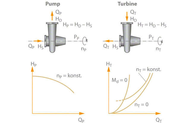
Fig. 1 Turbine mode: Difference between pump mode and turbine mode
The integration of a PaT (pump used as turbine) into a pressure control system is ideally performed via a bypass. line. As the centrifugal pump is not fitted with adjustable or variable pitch diffuser vanes external control devices (control valve I and II) are required in turbine mode. A shutoff valve should be installed upstream of the pump to enable its shutdown for maintenance work.
See Fig. 2 Turbine mode
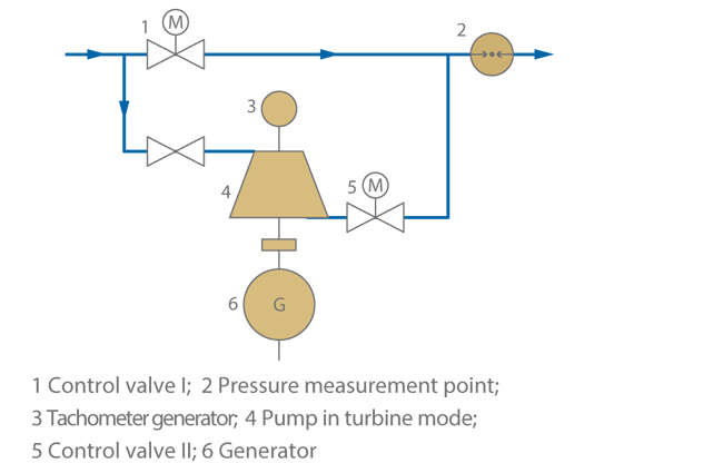
Fig. 2 Turbine mode: Pressure control system with pump used as a turbine, installed in the by-pass line
Feeding the recovered energy into the electrical grid via an asynchronous motor used as a generator is both an economical and technically straightforward procedure, with the unit's speed (apart from a load-dependent minor slip) being kept constant. An even simpler way of utilising the recovered energy is to aid or replace an installed electric motor by directly connecting the PaT to a machine.
Generating electricity for isolated operation requirements is possible. However, elaborate control is required to maintain a constant frequency in the event of fluctuating system loads. See Fig. 3 Turbine mode
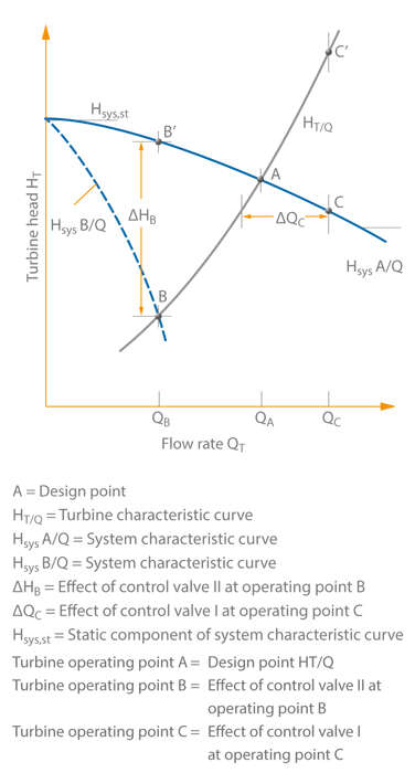
Fig. 3 Turbine mode: Centrifugal pump in turbine mode running at constant speed; pressure control via control valves I and II as shown in Fig. 2 Turbine mode
Similar to the pump's operating point, the turbine's operating point is given by the intersection between the turbine characteristic curve HT(Q) and the system characteristic curve Hsys(Q). If the volume flow demand decreases, the constant speed PaT (pump used as turbine) is no longer able to exploit the pressure potential available (point B). As a consequence, the excess energy ΔHB must be reduced via control valve II to ensure that a constant pressure is maintained on the outlet side.
If the volume flow requirement rises to point C, the increased volume flow rate QC is obtained by opening control valve I. The PaT alone would reduce the pressure too much (point C') which would lead to a drop in pressure on the outlet side.
The pressure downstream of the control system serves as controlled variable for throttling valves I and II.
The use of a constant speed machine results in the above-mentioned problems: The PaT is only designed for a defined volume flow rate and a defined pressure gradient. All other operating conditions must be controlled by the throttling elements.
The energy potential is not fully exploited. The PaT and its control equipment are, however, straightforward technical components which are favourably priced and easy to operate. In many instances a reverse running standard asynchronous motor is suitable for use as a generator.
When using a variable speed generator instead of an asynchronous motor, it is possible to vary the volume flow rate (QT) at a constant turbine head (HT) without additional throttling devices.
The pump to be used as turbine is selected to ensure that its flow rate coincides with the most frequently required volume flow. If the system's operating mode changes, i.e. if a lower flow rate is required, the rotational speed is increased; if, however, the volume flow demand increases, the speed is reduced.
This fact has a negative effect on the overall efficiency of the system. While efficiency drops very sharply with increasing speed, constant pressure reduction and thus a decreasing volume flow rate, the PaT's operating limit is very quickly reached with increasing volume flow rate and thus a decreasing speed (approx. 1.5 times the volume flow rate at BEP (QT.BEP)).
The energy account of a pump/turbine combination is balanced, which means that the turbine output power is equal to the pump output power.
The pump/turbine set thus serves as an energy converter, and there is no need to connect it to an electric motor.
Compared with conventional turbines, pumps used as turbines offer a range of both benefits and drawbacks.
See Fig. 4 Turbine mode
| Advantages | Disadvantages |
| Broad performance range offered by a closely spaced selection chart of standard pumps | Due to the lack of control equipment, possibilities for matching the system to actual demand are very low |
| Wide range of selection options with regard to materials, sealing elements and other accessories | |
| Favourably priced standard products | Slightly inferior efficiencies compared with turbines designed and manufactured to order for particular specifications |
| Short delivery times | |
| Use of ring-section pumps if high turbine heads and low flow rates are required | |
| Minimum control and monitoring | No adjustable diffuser elements |
Fig. 4 Centrifugal pumps in turbine mode
Centrifugal pumps and turbines are turbomachines which either transfer energy from a rotor to a fluid or from a fluid to a rotor. This relationship is expressed by the Euler equation.
See Fig. 5 Turbine mode
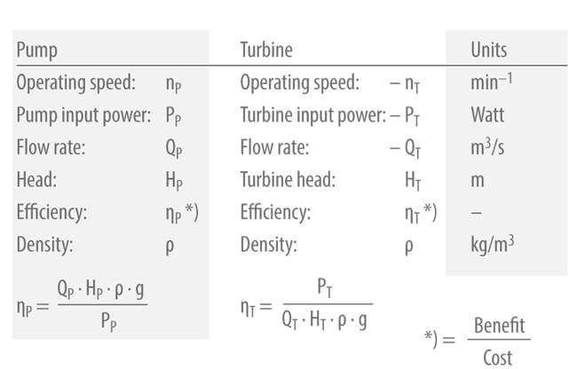
Fig. 5 Turbine mode: Nomenclature
Important characteristic curves for turbine mode
See Fig. 6 Turbine mode
See Fig. 6 Turbine mode
- Resistance curve a: No-load curve at torque (T) = 0
- Resistance curve b: Operating curve at constant speed (n)
- Resistance curve c: Resistance curve at locked rotor, speed (n) = 0
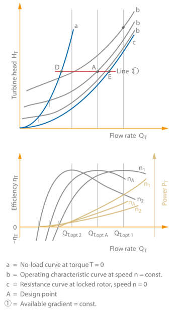
Fig. 6 Turbine mode: Turbine selection chart of a standard centrifugal pump with radial impeller
So far, only the operating curve (b) has been considered for the selection of the pump used in turbine mode. The resistance curves (a, c) with torque (T) or rotational speed (n) equalling zero are only relevant in the event of malfunctions. If the power output at the shaft is not used, for instance, due to an electric mains failure, the PaT (pump used as turbine will adopt the operating point which is the intersection of the system characteristic curve and the no-load curve.
If the system characteristic curve is assumed to have a constant gradient, then point D can be determined on line 1. The speed at this point (see Runaway speed) is considerably higher than the operating (nA) and is reached within a very short time following the sudden removal of the load on the generator.
In order to prevent damage to the PaT/generator set as a result of these operating conditions, both machines must be designed to withstand the resulting circumferential speeds. The rotational speed change is accompanied by an equally abrupt reduction in the volume flow rate which results in considerable pressure surges in the piping and in an additional, short-term increase in speed.
The resistance curve (c) shows the H / QT curve at locked rotor.
In the region of the design point A, the operating curves b of radial impellers are located close to the resistance curve c and, in the overload region, they run almost parallel to it at a relatively small distance. This physical characteristic can be utilised to reduce the risk of surge pressure. For this purpose the PaT is fitted with a quick-locking brake which becomes immediately operative upon generator load rejection to prevent the turbine set from reaching the runaway speed. The turbine set is decelerated to zero speed. The new operating point on the resistance curve c is located at point E. See Fig. 6 Turbine mode
The resultant change in volume flow rate (ΔQ) is, however, significantly lower than that which would result from operation at zero torque. Fig. 6 also shows the development of efficiency ηT and power PT as a function of flow rate QT.
