The "A" stands for analog and the "D" for digital. An analog-digital converter is an electronic component that converts analog input signals into digital data using different methods. These are then processed further and saved in digital format.
In the case of standard centrifugal pumps where there are no special measures to inhibit wear, the permissible solids concentration and, where applicable, the grain diameter and flow velocity are limited on the basis of empirical values.
In the case of centrifugal pumps, special measures are required in terms of the design or the materials to deal with the hydraulic solids transport.
For example, the pumps used within this context have robust external bearings and strong shafts. In addition, the walls are thicker in those areas where abrasive wear is anticipated. Highflow velocities are avoided whenever possible and in turn this generates only slight differences in pressure.
Those components that are likely to suffer wear after a certain operating period are designed so that they can be replaced with a minimum of effort and interruption time. The lined pumps are constructed according to this principle, in that their wear parts (hard-facing) are made from extremely hard materials and so only need to undergo machining at a small number of points.
A large number of pumps also feature speed control, which makes it possible to extend the operating period once the equipment starts to be affected by wear in spite of the increasing unbalance and the decreasing head. In narrow controlled gap seals, solids cause sliding wear. This can be countered by flushing with clear water (which is very elaborate during operation) or by using very wear-resistant materials.
The effects of material hardness and the angle of impact are governed by the following factors: If the solid particles strike a hard and brittle surface at a large angle of impact (approximately 90º), after causing initial compression and subsequent fatigue in the material, they then cause particles to be released from the material. Tough materials suffer less damage as a result of this kind of wear caused by collisions and impacts.
If the solid particles hit a soft surface at a small angle of impact (approximately 15°), they rub off material particles in the same way as during grinding. Hard materials are less affected by this scouring (hydroabrasive wear). See Fig. 1 Abrasion
Fig. 1 Abrasion: Wear intensity as a function of material and angle of impact
As most abrasive damage is caused by scouring, it is advisable to use very hard materials (e.g. NORIHARD®, chilled silicon casting, NIHARD®, hard-facings with tungsten carbide or cobalt alloys, ceramics).
Only a few parts of the pump are subjected to wear caused by collisions or impacts. These include the leading edges of casing tongues, impeller and diffuser vanes (seevane) as well as the front sides of baffles that face against the flow. At these points, wear-resistant and tough materials should be used. See Fig. 2 Abrasion
Fig. 2 Abrasion: Wear-prone areas in a volute casing pump
The absolute pressure sensor is a measuring device (also see Sensor) for converting the physical quantity of "absolute pressure" into a corresponding digital output variable when atmospheric pressure is measured, for example.
Absolute pressure sensors are used in barometers to measure the atmospheric pressure. They are also used in altimeters working on the barometric principle to measure the prevailing atmospheric pressure at a measuring location.
The concept of absolute velocity is mainly used in turbomachinery design and defines the velocity of a fluid particle in relation to the surrounding, stationary environment. Together with the relative velocity (➔w) and thecircumferential speed(➔u), it forms the velocity triangle.
The AC mains supply is also referred to as single-phase alternating current and corresponds to a voltage of 230 V at a frequency of 50 Hz in most European countries. North America and parts of Japan are different, however, and use 120 volts (rounded from 117 volts) at 60 Hz.
Acceleration due to gravity is the acceleration (which varies according to geographic location) caused by the earth's gravitational field which a body experiences irrespective of friction when in freefall to the earth's surface.
The symbol is g. The exact individual values are dependent on the centrifugal force resulting from the earth's rotation, the earth's oblateness and the elevation profile, and vary from one another by less than 7 ‰. The average value is 9.81 m/s2, as is also used in centrifugal pump technology. It is also used in accordance with ISO 9906 and EN ISO 17769-1 in many definition equations.
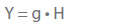
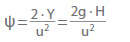
In a weightless or almost weightless state (e.g. in a satellite station), the head (H) of a centrifugal pump tends towards infinity because g ≈ 0, as a result of its definition. In the case of any centrifugal pump installed a long distance away from the earth, the finite specific energy (Y) should be adopted instead of the head. It is the useful mechanical energy transmitted by the pump onto the fluid, per unit mass of fluid handled (the latter being independent of the acceleration due to gravity). The same applies in accelerated or retarded systems (e.g. in a rocket). The following correlation exists between specific energy (Y) and the head (H):
Acceptance tests are often also referred to as acceptance testing. This process consists of carrying out a test in order to verify the technical guarantees agreed between the customer and the contractor in the supply contract by measuring the guaranteed quantities. The process is subject to defined acceptance test codes. Furthermore, the acceptance test can be used to check other technical quantities and properties of the pump insofar as these form part of the technical guarantee. These include stable H/Q curve, power input at zero flow and maximum power input, reverse running speed, leakage, smooth running and noises.
Possible locations for the acceptance test are the pump test facility belonging to the pump manufacturer or a neutral institution or, in the case of centrifugal pumps with very high input powers and casings that cannot be dismantled (e.g. aconcrete casing pump), the pump installation at the actual site. The location, time, scope and costs of the acceptance test must be agreed in the supply contract. See Fig. 6 Cooling water pump
Before the acceptance test is carried out, the customer and contractor should clarify the following issues and the answers should be incorporated into the order confirmation: Which acceptance test codes are to apply? What measurement uncertainties are permissible? Which operating points can be tested on the pump test facility using cold water or the actual fluid that is to be handled? Is the pump to be operated at full rotational speed or can it be run at a reduced speed? Which efficiency scale-up formulae are to be applied? Which operating conditions prevail in the installation when the acceptance test is carried out or still need to be created?
When comparing the efficiency calculated from the measured data with the guaranteed efficiency, the issue of bonus (target exceeded) or malus (target undershot) may also play a role.
The term "acceptance test codes" refers to the guidelines for carrying out an acceptance test. These are generally stipulated in the form of a standard.
What the acceptance test codes contain
Stipulations concerning technical guarantees and their fulfilment
Recommendations concerning preparation for and performance of guarantee checks
Recommendations for drafting the test/acceptance report
Definition of all the quantities that need to be measured and calculated (speed, pressure, torque, head,flowrate, NPSH values, power input and efficiency) in order to verify that all the guaranteed values specified in the contract of sale have been achieved
Description of the permissible metrology methods for verifying the guaranteed values as well as the permissible procedures for carrying out and evaluating the measurements while taking account of the overall measurement uncertainty
Stipulations for the comparison of measurement results with guaranteed values and the drawing of conclusions from this comparison
Recognised acceptance test codes
DIN EN ISO 9906 Rotodynamic pumps: Hydraulic performance acceptance tests - Grades 1, 2 and 3
Hydraulic Institute (HI) Standards, Section: Centrifugal pumps, test standards (Cleveland, USA)
The acceptance rules mentioned above are the international standard rules for pump testing.
In addition to the recognised acceptance test codes, the following regulations are used for assessment purposes in specific scenarios:
Regulations for special cases
DIN 4325 Field acceptance tests of storage pumps
IEC Recommendation, Publication 198, International Code for the Field Acceptance Test of Storage Pumps
API Standard 610: Centrifugal Pumps for General Refinery Services, Section 4: Inspection + Tests; Section 5: Guarantee + Warranty
ASME PTC 8.2 Centrifugal Pumps Power Test Code
DIN 1184 Pumping stations
DIN 4047-2 Water engineering of agricultural lands
Acceptance testing is also often referred to as an acceptance test. In this context, the term "acceptance“ is meant in a technical, rather than a legal, sense. Hence a successfully completed acceptance test does not in and of itself constitute "acceptance" in a legal sense pursuant to section 640 of the German Civil Code.
An accumulator is a vessel which is partly filled with liquid and partly with gas (often air); its internal pressure is generally higher than atmospheric pressure. Accumulators store fluids to be handled under increased pressure (e.g. in pressure booster systems) in order to attenuate surge pressures and serve as energy storage devices to prolong the run-down time of centrifugal pumps. A transient flow analysis determines the accumulators' size and the valves, compressed air supply connections and instrumentation used.
Accumulators for automatic pressure control in water supply systems (see Pressure booster system) are usually installed vertically; horizontal installations are rare. See Fig. 1 Accumulator
Fig. 1 Accumulator: Automatic pressure control in water supply systems
Accumulator size is determined by the pump set's number of starts per hour (Z). The number of start-ups depends on a variety of factors; information on the frequency of starts should be obtained from the electric motor suppliers (see Frequency of starts).
At start-up pressure (pe), the lowest water level selected must ensure that air can under no circumstances enter the discharge line. The accumulator volume (V) should therefore be selected so that it is 25 to 40 % larger than the effective accumulator volume (J) required. A compressed air shut-off valve may be provided as an additional component. Its purpose is to prevent compressed air entering the discharge line. In the case of unfavourable piping layouts (e.g. in domestic water supply systems) and horizontal vessels, the water level must be checked; if necessary, the connection must be placed at a lower level (e.g. dome).
A safety allowance of 25 % is included in the equation given below for accumulator sizing.
New Content Item (1)
Fig. 2 Accumulator: correction value K
The proportion of usable water volume (S) in relation to total volume (V) depends solely on the start-up and stop pressures and can be calculated as follows:
New Content Item (1)
In set-ups with more than one of the same pump, increasing the number of starts and stops by periodically switching between the pumps allows a reduction of accumulator size. Membrane-type accumulators are often provided for smaller units; these eliminate the need for a compressed air shut-off valve or a compressor. In this case, an extra 25 to 40 % of volume in addition to the effective volume (J) is not required.
The number of pumps in a pressure booster system has no bearing on the calculation of the accumulator volume. If several pumps with different flow rates are employed, the mean flow rate of the largest pump should be used in the equation. For systems in which several pumps are flow-controlled, and only the base load pump is started and stopped as a function of pressure, the accumulator size should be calculated in relation to this base load pump.
A sub-division of the calculated accumulator volume between several accumulators is desirable if such smaller vessels can be accommodated more easily in the available space, and the system costs are thereby reduced. When dividing the volume between two accumulators, the pressure settings for pump start-up and stopping can be set in such a way that the second accumulator is filled with air only.
If the volume is divided between more than two accumulators, these must be connected via the gas (air) side to ensure that each accumulator is evenly used. See Fig. 3 Accumulator
Fig. 3 Accumulator: Schematic for a water supply system as pressure booster system
As a proportion of the accumulator's air content is gradually absorbed by the water under pressure, the compressed air in the vessel must be topped up from time to time, usually by means of a compressor. The compressor size is determined by its suction capacity (Qk). Compressor selection depends on the time (T) required to fill the whole accumulator volume. It is assumed that only two thirds of the accumulator volume (which corresponds to the water level at stop pressure) must be filled with compressed air. The filling time should not exceed eight hours. The suction capacity in m3/h is:
New Content Item (1)
The compressor's operating pressure should as a minimum correspond to the pump's maximum stop pressure. The safety valve on the compressor must be pre-set so that the maximum permissible operating pressure of the accumulator is not exceeded.
In accordance with the accident prevention regulations for pressure vessels (German Gas and Waterworks Professional Association, Düsseldorf), fitting a safety valve on accumulators for centrifugal pumps is not mandatory as long as the H/Q curves (see Characteristic curve) of the pumps do not exceed 1.1 times the maximum permissible operating pressure for the vessel, and steps are taken to prevent critical overspeeding of the pumps.
The accumulators are welded, cast, riveted and, occasionally, finished in strip-wound construction (for very high pressures and temperatures in the chemical industry). The materials used are steel plate (boiler plate), non-ferrous metal plate, cast steel and plastic. The design and operating data of commonly used accumulators are standardised.
Principal standards, directives and regulations applicable to accumulators
American Petroleum Institute: API 610
American Society of Mechanical Engineers: ASME-Boiler and Pressure Vessel Code Section I-X
German Pressure Vessel Society: AD regulations
Federal Ministry of Economics: Protection of Labour Act (Federal Bulletin 4/1980) and Steam Boiler and Pressure Vessel Act
DIN EN ISO 11117, DIN 4810
German Organisation for Technical Standards in the Gas and Water Industries (DVGW): DVGW Worksheet W 314
TRD Technical Rules for Steam Boilers
German Federation of Technical Supervision Associations
Regulations of shipbuilding classification societies, e.g. German Lloyd (GL)
An actuator is a control element used to intervene in a process. It converts switching information provided by the control system into physical force and typically regulates mechanical work, such as opening and closing valves, via signals. In control systems, actuators form the counterpart to sensors.
The adjustment mechanism is agear unit, which allows small propeller pumps to be manually adjusted. The axial movement of the rod is translated into a rotating movement of vane trunnions and thus the vanes themselves. See Figs. 1, 2Impeller blade pitch control
The aerofoil theory has gained increased importance in the calculation of axial blading (impeller, diffuser, blade/vane) For the calculation, the blade/vane is, however, viewed as an aerofoil wing in conjunction with a cascade (see Vane cascade) The lift and drag coefficients and other characteristics of the aerofoil wing dependent on its incidence angle are mainly established experimentally (e. g. in a wind tunnel with three-component force measurements) but can also be calculated theoretically (analytically and/or using CFD).
The aerofoil theory allows the frictionless incompressible approach flow (seePotential flow) of an aerofoil of unlimited width to be calculated, using either conformal representations (transformation back to the flow around a cylinder) or the method of singularities (simulation of vortices, sources and sinks along the aerofoil's centre line or simply of vortices along the aerofoil's contour). In its extended form, the method of singularities can also be applied to vane cascades.
When investigating flow phenomena, cost factors often favour the use of models which are geometrically similar to the original, full-sized equipment (see Similarity conditions).
For this type of testing it is necessary that models are not only geometrically similar, but are also subjected to similar physical conditions.
The physical laws (differential equations including boundary conditions) applied must remain invariant under similarity transformations. This is achieved by dividing all relevant physical quantities by exponential products characteristic of the configuration to be tested so as to obtain ratios of the unit 1.
of the original and the model are the same. The relationships established between the physical quantity of the original and that of the model by means of the characteristic coefficients are called affinity laws.
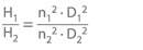
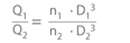
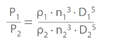
The following model laws thus apply to two geometrically similar centrifugal pumps operating under physically similar conditions:
Affinity laws
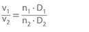
Flow velocity in a cross-section
Pressure
Specific energy
Head
Flow rate
Power input (assuming identical pump efficiencies)
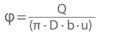
Flow coefficient
Head coefficient
If Δhs = Y (see Specific energy) is inserted, the pressure coefficient in its known form can be established:
As pump efficiencies are more or less dependent on friction conditions, they are subject to other conversion laws (see Efficiency scale-up). The selection of characteristic quantities to determine the characteristic coefficients is largely arbitrary. For instance, when studying the theory of flow in radial impellers (see Impeller) , the impeller's circumferential speed (u), its outlet diameter (D) and the outlet width (b) of the vane passage are selected as characteristic quantities. These are used to establish two characteristic coefficients, where Δhs is the isentropic increase (see Entropy) ) of the generalised specific enthalpy of the fluid handled.
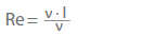
As a general rule, a length (l) and a velocity (v) are selected as characteristic quantities for flow investigations. Flows subject to friction are characterised by the kinematic viscosity (ν). The Reynolds number (Re), can be derived from these and also gives the ratio of inertia force to friction force.
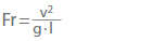
If gravity has to be taken into account as an external force, the characteristic coefficient of the acceleration due to gravity is g · l / v2. Its reciprocal value is the Froude number (Fr).
It expresses the ratio of inertia force to the force of gravity. If further physical phenomena such as compressibility, heat transfer and surface tension etc. have to be taken into account, further characteristic coefficients must be introduced.
As characteristic coefficients are not independent of one another, it becomes impossible to achieve physical similarity when multiple characteristic coefficients require consideration.
Model tests are widely used to investigate fluid mechanics, design strength and heat transfer problems.
Aggressiveness describes the effect of a substance on its environment. Descriptive characteristics include: flammable, alkaline, acid-free and anhydrous (also see chemical resistance table).
Air lift pumps are also known as mammoth pumps, gas lifts or L�öscher pumps, and are used for lifting liquids laden with solids. For this purpose a gas is injected below the liquid level, via a compressor, into the pipe, which is immersed vertically into a liquid (also see Type of pump).
The function of air lift pumps is based on the lift action of a mixture of liquid and gas (see Two-phase flow). They can therefore only be used in pump systems with sufficient geodetic head differences.
The air vessel is used as an accumulator to store compressed air, to separate condensate through cooling and to compensate for pressure fluctuations in a compressed air distribution system. In water supply systems, air vessels are used as hydrophors and also as safety components to avoid surge pressure.
Alternating current is internationally abbreviated as AC and describes the electrical current that periodically changes its direction (polarity), usually sinusoidally. This periodic change is expressed as frequency
and indicates the number of changes in current direction per second.
In technical terms, the benefits of alternating current are that it is easy to generate and transform the voltage for the low-loss, long-distance transmission of high-voltage alternating current, and it is easy to convert from one voltage to another using a transformer. Consequently, alternating current is used primarily in public electrical power networks. With sinusoidal alternating current, the instantaneous values across a complete period, with one positive and one negative half-wave (alternation), exactly match the values of the sinus trigonometric function across a full circle (0 - 360 degrees). See Fig. 1 Alternating current
Fig. 1 Alternating current: Flow of current and voltage of sinusoidal alternating current for a purely ohmic load
Normal AC mains supply is synonymous with single-phase alternating current and, in Germany and other European countries, corresponds to a frequency of 50 Hz and a voltage of 230 V. In North America and parts of Japan, however, mains frequencies of 60 Hz with voltages of 120 V (rounded from 117 V) are used.
In practice, assembling three coils in the generators creates three separate "phases" of alternating current instead of just one alternating current.
They are evenly distributed around the periphery. These coils produce separate alternating voltages, each of which is staggered by a third of a period (equating to 120 degrees in a circular orbit) compared with other coil voltages. The individual phases of industrial alternating current can be used independently of one another as separate systems for small consumers.
The alternating current is usually distributed to the customers with the three phases (L1, L2, and L3), a neutral conductor (N), and an earth (PE) conductor. See Fig. 2 Alternating current
Fig. 2 Alternating current: Three-phase system with neutral conductor (four-conductor system) asymmetrically loaded by different consumers
A special form of alternating current is three-phase alternating current, as used in public power networks to distribute large amounts of electrical energy. For motor drives, this type of current offers robust electric motors of particularly simple design.
Amortisation or payback are terms used to describe whether and at what point the revenue achieved during the operation of a pump or pump system (also see Economic efficiency) equals the necessary investment costs.
The signals processed during analog data transmission continually represent the physical quantity assigned to the signal, whereby every value is permitted in defined intervals (also see Communications system).
An analog interface is an electrical connection that forwards analog electric signals to downstream electric and electronic devices or components for further processing. Standardised analog interfaces (e.g. 0/4 - 20 mA and 0/2 - 10 V) are also referred to as standard signals.
Since current signals are not sensitive to electromagnetic interference (activation of adjacent consumers) and loss of voltage (due to line resistance), they are preferred over voltage signals. The maximum length of a signal cable for the power source is only limited by the maximum load.
The load is the load resistance of an electrical transducer/converter with current output signal, whereby the cable resistance defined by the cable cross-section must be taken into account.
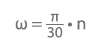
Angular velocity indicates how quickly a rotating body is moving in relation to its axis of rotation, irrespective of its radius. It is proportional to the rotational speed and is quantified in rad/s.
The relationship between angular velocity and rotational speed is:
ω Angular velocity in s-1 n Rotational speed in min-1
Application software is used to process an application-specific task on a computer and should not be confused with the software that runs the computer. It is installed over the computer's system software and uses the functions it provides to process the task at hand.
The Archimedean screw pump is used for constant-pressure lifting of a fluid to a given geodetic height with the aid of a rotating screw (true helicoid), which works on the principle of the irrigation device invented by Archimedes. See Fig. 1 Archimedean screw pump
Abb. 1 Schneckentrogpumpe: Schematischer Aufbau
The screw is open on all sides, can be several metres long, is usually made of sheet metal and can have up to three flights or starts. It rotates in an open, semi-circular trough inclined at an angle of approximately 30°. At each turn, the screw scoops up a limited volume of water (determined by the angle of inclination, diameter and lead or pitch of the screw) from the lower water reservoir and lifts it to the top end of the trough at a relatively low rotational speed (below 100 rpm).
Depending on the immersion depth of the screw's bottom end, the volume flow rate of the Archimedean screw pump adjusts automatically within certain limits as the volume of liquid in the individual flights changes. This operating principle presupposes that the screw is constantly submerged in the liquid to at least half the diameter of its leading screw passage and that the clearance gap width between the screw and the sheet steel or concrete trough is not too large (so as to minimise leakage).
The lower bearing is submerged (see Plain bearing) and must be lubricated with fresh water or grease. The upper bearing often is a rolling element bearing and also absorbs axial forces The gear unit is coupled to the upper end of the screw.
Archimedean screw pumps are capable of pumping heavily contaminated surface water or sewage, and even sand if they are specially designed for this purpose. The head is purely geodetic and ranges up to 6 m at efficiencies between 60 and 80 %. Depending on the flow rate the screw diameter can be up to several metres. Archimedean screw pumps are simple, adapt easily to operating conditions and operate economically. However, they frequently have to compete with submersible motor pumps.
The area ratio is used to calculate the required hole diameter of an orifice, and is determined via the inner diameter of the orifice (dOr) and the inside pipe diameter (D).
An asynchronous motor has a passive rotor that is short-circuited permanently (squirrel-cage rotor) or temporarily (see Slip ring rotor). It can produce up to several megawatts and is most frequently used as a standard three-phase motor in industrial applications.
The magnetic field in the asynchronous motor is generated by a magnetising current via the electrical energy provided. Asynchronous motors are characterised by slip, i. e. a load-dependent difference between the rotor speed and the speed of the rotary field of the supply voltage.
The rotor is a metal cage with axial bars arranged in a symmetric circular pattern and fixed to a short-circuit ring (end ring) at each end.
The stator comprises distributed coils that induce voltage into the bars of the rotor (see Induction) by way of a rotating magnetic field. This results in a high flow of current in the short-circuited bars, which exerts a force between the rotor and stator in the magnetic field and leads to the electromagnetic interaction responsible for the asynchronism. Asynchronous motors are subject to significant losses in the stator and rotor.
In slip-ring rotor motors, the three-phase rotor winding connects to variable resistors – typically used as liquid starters – via the slip rings. This design ensures a soft start-up process that does not place a shock load on the power supply mains and allows the speed to be changed to a certain extent. However, it also produces significant power loss.
The rotor windings of a squirrel-cage rotor generally consist of single or twin conductor bars that are short-circuited at their ends by a ring-shaped conductor. Squirrel-cage rotors are very simple in design and reliable, and they do not require maintenance. See Fig. 1 Asynchronous motor
Fig. 1 Asynchronous motor: Sectional view of asynchronous motor
A distinction is made between dry rotor, submersible and wet rotor motors with respect to water contact. See Fig. 2 Asynchronous motor
Internal wetting
External wetting
Rotor
Winding
Dry housing
Wet housing (submersible motor)
Dry
Dry
Dry motor (with or without protection against ingress of water)
Dry (air-filled) submersible motor
Wet (wet rotor motor)
Dry (canned motor)
Wet rotor motor of a glandless pump
Fully submersible (fluid-filled) motor
Fig. 2 Asynchronous motor: Designation of asynchronous motors depending on wetting
The dry motor has different types of protection against ingress of water (see Type of protection).
The submersible motor is partially or completely immersed and is usually installed in a vertical position. Heat generated by the motor is transferred directly to the surrounding fluid handled. Its defining feature is its motor housing, which is wetted from the outside (see Submersible motor pump). Internal wetting and immersion depth distinguish oil- or air-filled submerged motors for small to medium immersion depths (waste water submersible motor pumps) from fully submersible motors.
Fully submersible motors are wetted by the fluid handled on the inside and the outside. They are built for any immersion depth and are above all used in boreholes (see Submersible borehole pumps) which is why they have a small diameter and are relatively long. Fully submersible motors can be equipped with a wet stator winding (including water-tight plastic insulation) or, in conjunction with a can, a dry winding (see Canned motor pump).
The wet rotor motoris filled with a liquid and, unlike the submerged motor, its housing is not wetted from the outside. It has liquid-lubricated bearings (see Plain bearings) and forms a hermetically sealed pump set (glandless pump) together with the pump. The motor can be equipped with a wet stator winding or, in conjunction with a can, a dry winding and is frequently the motor of choice for circulating pumps.
The acronym ATEX is the French abbreviation for "Atmosphère explosible" and refers to the two European Union (EU) directives covering the area of explosion protection: ATEX Equipment Directive 94/9/EC (also referred to as ATEX 95) and ATEX Workplace Directive 1999/92/EC (also referred to as ATEX 137). These directives lay down rules for placing products on the market and operating them in hazardous areas. They are designed to protect people within these areas by means of basic health and safety requirements (see also explosion protection).
In centrifugal pump technology, the term refers to the absolute atmospheric pressure at the installation site of the pump, averaged over an extended period of time. In most cases, the atmospheric pressure can be taken as equal for the elevations of both the inlet and outlet cross-sections of the pump system. As the altitude increases above mean sea level (MSL), the atmospheric pressure decreases. See Fig. 1 Atmospheric pressure
Altitude above MSL
Atmoshperic pressure
m
Pa
mbar = hPa
0
101300
1013
500
95500
955
1000
89900
899
2000
79500
795
Fig. 1 Atmospheric pressure: Atmospheric pressure depending on altitude, based on 1013 mbar ("physical atmosphere") at 0 m above MSL
The averaged atmospheric pressure should only be substituted for the absolute atmospheric pressure (which varies by location and time) in rough calculations of the head, NPSH (net positive suction head), etc. The unit of atmospheric pressure is the Pascal (Pa); in centrifugal pump technology however, the unit of bar or mbar (= hPa) is generally used.
The automatic circuit breaker is also known as the automatic switch and is a type of electrical remote control switch. It combines the switch (see Electrical switchgear) and the overcurrent protective device. During a short circuit or overload, the automatic circuit breaker trips but is ready for operation again, unlike other fuses.
Automatic switches perform the switching operation automatically via electrical switchgear, whose coil current is controlled via momentary or maintained contactors.
Automation describes the process by which machines are used to perform work that would otherwise be carried out manually. Put technically, automation refers to the transfer of a performing function to a machine. In automation systems, measuring, control, regulation, and digital methods are leveraged to control or monitor one or more manual worksteps. In pump systems, automation technology enables open-loop control closed-loop control and speed control of motors.
Availability is an indicator of the reliability of an installation, a system or a machine. It may be defined as the ratio between the number of operating hours plus stand-by hours during a given period, on the one hand, and the overall length of the given period, on the other. Thus, the availability indicates the probability of a machine (for example) being operable at a particular point in time.
An axial flow pump belongs to the family of flow pumps. It is fitted with an axial flow impeller and transports the fluid handled by making use of the pressure differences at the impeller vanes.
FJ = ρ · Q · Δvax Q Flow rate ρ Densityof the fluid handled Δvax Difference between the axial components of the absolute velocity at the impeller inlet and outlet
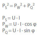
The resultant pressure forces arising from the static pressures up- and downstream of the shaft seal (ss) on the relevant shaft cross-section Ass: FWd = AWd · ΔpWd
Special axial forces, e.g. when changes to the vortex conditions in the clearances between impeller and casing (side gaps) occur during the start-up process (see Disc friction)
Other axial forces such as the force of the rotor weight (FW) on non-horizontal centrifugal pumps or magnetic pull in theelectric motor(Fmech), e.g. in close-coupled pumps
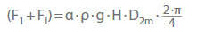
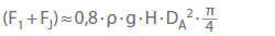
The axial thrust component (F1 + FJ) of closed impellers (i.e. with suction-side shrouds) which are not hydraulically balanced is:
α Axial thrust coefficient (based on experience) ρ Density of fluid handled g Gravitational constant H Head D2m Mean impeller diameter:
The axial thrust coefficient is essentially dependent on the specific speed (ns) For radial and mixed flow impellers the following equation applies in the range of 6 < ns < 130 rpm :
α=0,5 · (Dsp/D2m)3 + 0,09 ≈ 0,1 − 0,3
Dgap seal Diameter of the controlled gap seal at the suction-side impeller shroud
See Fig. 2 Axial thrust
Fig. 2 Axial thrust: Non-balanced impeller design with conical impeller outlet area
This equation applies to flow rates (Q) of 0.8 · Qopt to 1.0 · Qopt and to the clearance gap width s = 0,1 mm. If the clearance gap width is doubled, α increases by 8 %.
the axial impeller force (F1) is largely determined by the impeller's axial position in relation to the diffuser. In the case of open radial impellers with no shrouds on the suction side, the axial force (Fs) is much lower than on closed impellers, meaning that the axial impeller force (F1) is higher.
Open impellers with cut-outs in the impeller shroud between adjoining impeller vanes develop a lower pressure force (Fd), and, consequently, a lower axial force (F1) than impellers with a full discharge side shroud. See Fig. 13Impeller
For axial propellers, the axial thrust coefficient (α) is almost equal to the degree of reaction (rth). The axial thrust can then be roughly calculated using the propeller's outside diameter (OD):
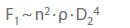
The following proportionality applies to the F1 component of the axial thrust (See Fig.1 Axial thrust) in the case of geometrically similar pumps at a defined rotational speed (n) and at the largest impeller diameter (D2):
The rotation of the fluid handled in the discharge-side and suction-side clearances between impeller and casing exerts a strong influence on the axial pressure forces (Fd) and (Fs). The mean angular velocity (see Rotational speed) of the rotating fluid handled reaches approx. half the impeller speed.
In addition, as a result of Coriolisaccelerations, the inward directed clearance flow in the suction-side (i.e. outer) clearance between impeller and casing (side gap) further increases the side gap turbulences. In the discharge-side (i.e. inner) side gap of multistage pumps whose impellers are not hydraulically balanced, the process is reversed as a result of the outward-directed gap flow. The vortex motion is decelerated resulting in an increase of the axial force Fd, and hence of F1.
The axial impeller force is higher during the start-up process than during steady-state operation, as during start-up rotation of the fluid handled begins slowly due to disc friction caused by the action of the impeller shrouds or the braking effect of the stationary casing surfaces.
Various forms of axial thrust balancing
Mechanical: complete absorption of the axial thrust via a thrust bearing (e. g. plain bearing, rolling element bearing)
Design-based: back-to-back arrangement of the impellers or stages (see Back-to-back impeller pump) and through the absorption of the residual axial thrust via a thrust bearing
Balancing or reduction of the axial thrust on the individual impeller via balancing holesSee Figs. 7, 9 Axial thrust
Balancing of the complete rotating assembly via a balancing device with automatic balancing (e. g. balance disc and balance disc seat) or partial balancing via a balance drum and double drum
Reduction at the individual impeller by back vanes (dynamic effect) See Fig. 8 Axial thrust
Mechanical axial thrust balancing
The absorption of the axial thrust by a rolling element bearing is the most efficient, cost-effective solution. However, if the absence of special balancing equipment requires the use of particularly complex thrust bearings, these benefits in terms of efficiency and costs may be eliminated.
Design-based axial thrust balancing
In the case of an impeller arrangement in a pipeline pump with four stages, each featuring a 2 x 2 back-to-back arrangement, a maximum of twice the normal axial thrust per stage can occur in the event that system conditions cause cavitation in two stages. See Fig. 5 Axial thrust
If, however, a more complex, parallel-coupled back-to-back impeller arrangement is chosen, only the normal axial thrust per stage occurs. See Fig. 6 Axial thrust
Both pump types must be equipped with thrust bearings of appropriate strength.
Fig. 5 Axial thrust: Axial thrust balancing in a four-stage pipeline pump with two opposed sets of two series-coupled impellers each
Fig. 6 Axial thrust: Axial thrust balancing in a four-stage pipeline pump with two sets of parallel-coupled opposed impellers
Axial thrust balancing at the impeller
This is the oldest method for balancing axial thrust and involves reducing the pressure in a chamber equipped with a throttling gap, usually down to the pressure level encountered at the impeller inlet. The pressure is balanced via balancing holes in the impeller.
These balancing holes may lead to variations in axial thrust balancing as a result of varying inlet conditionsSee Fig. 7 Axial thrust
Fig. 7 Axial thrust: Axial thrust balancing in a single-stage centrifugal pump with discharge-side sealing clearance and balancing holes
The angular velocity has a dynamic influence on the magnitude of the axial thrust (see Rotational speed). An increase in angular velocity is mostly achieved by back vanes die which are radially arranged on the rear side of the impeller.
The higher mean angular velocity of the vortices in the clearance between impeller shroud and casing results in a lower static pressure on the discharge-side impeller shroud. This results in a lower axial force Fd and thus a lower F1. See Fig. 8 Axial thrust
Most radial back vanes are designed with diameters (Dbv o, Dbv i), side space depth (a), vane height (h) and vane number (z) which vary according to requirements. The power absorbed by this method of axial thrust balancing depends on the sizing of the back vanes. The pump efficiency may drop by up to three points due to the back vanes. See Fig. 8 Axial thrust
Fig. 8 Axial thrust: Axial thrust balancing in a single-stage centrifugal pump with back vanes
A comparable effect is achieved when the impeller is balanced via the provision of balancing holes at defined areas on the discharge side without fitting a second discharge-side joint ring. The gap flow directed toward the inside creates an angular momentum in the space between the impeller shroud and the casing which increases the local angular velocity and, as a consequence, reduces the static pressure. See Fig. 9 Axial thrust
Fig. 9 Axial thrust: Axial thrust balancing in a single-stage centrifugal pump with balancing holes only
All hydraulic balancing devices are fully effective at optimal flow rate Qopt. Residual forces occurring under low-flow and overload, conditions must be absorbed by thrust bearings. See Figs. 7 to 9 Axial thrust
Axial thrust balancing via balancing devices
Available options
Balance disc with balance disc seat and balancing flowreturn line See Fig. 10 Axial thrust
Balance drum with balancing flow return line and thrust bearing See Fig. 11 Axial thrust
Double drum with balancing fluid return line and thrust bearing See Fig. 12 Axial thrust
In the case of the balance disc, the gap flow (see Clearance gap loss)is low because the self-adjusting axial gap (s) remains very narrow which means that the pump's efficiency is only slightly reduced. However, in the case of the balance drum, the radial clearance gaps are wider and therefore the gap flows are higher, causing a greater drop in efficiency which is then further compounded by the fact that an additional thrust bearing is required. See Fig. 11 Axial thrust
Labyrinth-type gap seals are fitted to minimise the high gap flow (e. g. double drum balancing devices). Thanks to its large axial clearance (s), double drum balancing devices allow an additional thrust bearing to be fitted which is mainly designed to prevent mechanical seizure in the balancing system. See Fig. 12 Axial thrust
Fig. 10 Axial thrust: Balancing device with balance disc
Fig. 11 Axial thrust: Balancing device with balance drum and thrust bearing
Fig. 12 Axial thrust: Balancing device with double drum and thrust bearing
Seizing may occur during start-up, during operation at extreme overloads (see Operating behaviour) or when cavitation takes place. The pump rotor's position and, consequently, the wear of the balancing equipment or thrust bearing can be ascertained by simple devices indicating seizure during operation.


")

")

")


 asymmetrically loaded by different consumers")