The term "immission" comes from the Latin word "immittere" and means to send in. From a legal perspective, it denotes the external impact on something such as the impact of light or noise on a body.
Immission Control Act refers to the German Federal Immission Control Act [Bundes-Immissionsschutzgesetz BImSchG]. Both terms are short designations for the Act on the Prevention of Harmful Effects on the Environment Caused by Air Pollution, Noise, Vibrations and Similar Phenomena [Gesetz zum Schutz vor schädlichen Umwelteinwirkungen durch Luftverunreinigungen, Geräusche, Erschütterungen und ähnliche Vorgänge].
It is part of the environmental protection legislation which is intended to protect people, animals, plants and real assets in Germany from harmful environmental effects, hazards, considerable disadvantages and sources of inconvenience as well as to prevent harmful environmental effects from occurring in the first place.
As a result, owners/operators of plant and machinery are required to ensure that members of the general public are not affected by any harmful environmental effects and do not suffer considerable disadvantages or inconvenience. The benchmark for the precautions taken to prevent harmful environmental effects is the current tried-and-tested state of the art.
In the context of centrifugal pump engineering, the Immission Control Act regulates the emission of harmful noise and vibrations as well as issues relating to the permissible rise in temperature of natural water bodies (e.g. that associated with cooling water supply for power stations).
An impeller is a rotating component equipped with vanes or blades used in turbomachinery (e.g. centrifugal pumps). Flow deflection at the impeller vanes allows mechanical power (energy at the vanes) to be converted into pump power output.
In accordance with EUROPUMP TERMINOLOGY and DIN 24250, a distinction is made between counter-clockwise and clockwise impellers, as viewed in inlet flow direction.
Depending on the fluid flow pattern in multistage pumps and the impellers' arrangement on the pump shaft impeller design and arrangements are categorised as: single-stage, multistage, single-entry, double-entry, multiple-entry, in-line (tandem) or back-to-back arrangement. Typical impeller arrangements are illustrated in Figs. 17 to 19 Impeller.
Depending on the flow line pattern in the impeller (especially in the outer impeller diameter area), impellers are subdivided into the following types:
Fig. 6 Impeller: Variants of a mixed-flow impeller showing the difference between a closed and an open impeller, a single-entry and a double-entry impeller a) Closed, single-entry impeller b) Open, single-entry impeller c) Closed, double-entry impeller
To accommodate the vanes, all impellers are equipped with a back shroud, and in the case of closed impellers also a front shroud (see Disc friction); depending on the perspective, these can also be viewed as an inner shroud and, in the case of closed impellers, an outer shroud. If an impeller has no front (outer) shroud, it is classed as an open impeller.
In order to achieve optimal pump efficiencies and minimum NPSHR values, the impeller must be provided with a certain number of vanes. Employing a low number of vanes increases the free, unimpeded flow cross-section through the impeller. This enables impellers to handle more or less contaminated fluids ( waste water pumps,pulp pumps) and solids (solids transport).
In practice, the number of vanes of radial flow and mixed flow impellers handling liquids containing sludge or solids is reduced to one, two or three vanes. These impellers are called channel impellers or single-vane impellers and can be either open or closed impellers. See Figs. 7 to 13 Impeller
Fig. 7 Impeller: Closed single-vane impeller (shown with shroud removed)
Fig. 8 Impeller: Open single-vane impeller
Fig. 9 Impeller: Closed single-channel impeller (shown with front shroud removed)
Fig. 10 Impeller: Closed two-channel impeller (shown with shroud removed)
Fig. 11 Impeller: Open two-channel impeller with S-shaped vanes
Fig. 12 Impeller: Closed three-channel impeller (shown with shroud removed)
Fig. 13 Impeller: Open three-channel impeller with cylindrical vanes
Closed single-vane impellers are used to pump fluids containing very coarse solids. They are characterised by a non-clogging free passage. The drawback of these impellers is the so-called hydraulic unbalance due to the asymmetrical pressure field. See Fig. 7 Impeller
Open channel or single-vane impellers are used to handle gaseous liquids. A single-vane impeller is referred to as an open, diagonal single-vane impeller (D impeller) if the flow lines in the impeller run diagonally outward. It is particularly suitable for untreated, solids-laden and gaseous waste water, as well as for fluids with a higher viscosity. See Fig. 8 Impeller
The blades of axial and mixed flow propellers (see Propeller pump) can be either fixed, adjustable (when the pump is dismantled) or of variable pitch type (see Impeller blade pitch adjustment).
In the case of adjustable or variable pitch blades, the contour or profile of the pump casing and of the hub in the adjustment region is usually spherical. This ensures that the internal and external clearance gap width at the hub remains constant for all blade pitch adjustment angles. See Fig. 4 Impeller The free-flow impeller and the peripheral impeller represent special impeller types. See Figs. 14 to 15 Impeller
Fig. 14 Impeller: Free-flow impeller
Fig. 15 Impeller: Peripheral impeller
When selecting a pump for a given flow rate (Q) and a given head(H)the impeller type is decisive. Free selection of an axial, mixed flow, radial or peripheral impeller type is restricted by the fact that the values for the anticipated rotational speed(n) and the anticipated impeller diameter (D) must not be too extreme. The ability to achieve optimum pump efficiencies or stage efficiencies at a specific speed (ns) is therefore dependent on specific impeller designs:
Radial impeller ns ≈ 12 to 80 rpm
Mixed flow impellers ns ≈ 80 to 160 rpm
Axial flow impellers ns ≈ 160 to 400 rpm and higher
Impeller blade pitch control is used in propeller pumps with axial and mixed flowimpellers to change the pitch of the impeller blades during operation. At constant rotational speed, impeller blade pitch control changes the flow rate, head and power input. of the pump, enabling optimal closed-loop control with low losses. Considerable outlay is required for this configuration, however. The impeller blade pitch control method most frequently used in centrifugal pumps takes the form of an axially displaceable, bearing-supported adjusting rod in a hollow pump shaft. It can absorb adjusting forces of up to 600 kN in large cooling water pumps, for example, or even greater forces in special-purpose applications. The adjusting rod is moved in the axial direction by a mechanical screw actuator or hydraulic piston.
See Fig. 1 Impeller blade pitch control
Fig. 1 Impeller blade pitch control: Gearing for actuating the adjusting rod in the pump shaft
On smaller propeller pumps, blade pitch is frequently adjusted manually with transmission gearing (also see Adjustment mechanism). See Fig. 2 Impeller blade pitch control
Fig. 2 Impeller blade pitch control: Mechanical gearing for adjusting the blades of a mixed flow propeller
The impeller blade pitch can also be adjusted by an adjustment mechanism which is fitted in the impeller hub, together with the hydraulic or electric actuator, or by adjustment mechanisms which rotate the blade trunnions via rotation of the adjusting rod. Impeller blade pitch control as applied to centrifugal pumps evolved from early designs used for ship propellers and water turbines.
The outer profile (see Flow profile) and inner profile (hub profile) of the adjustable blades must be located on concentric spherical surfaces to avoid efficiency-reducing gaps (see Clearance gap width). This design requirement determines the shape of the pump casing and the impeller hub in the flow area of the impeller. The spherical shape is not always favourable from a hydraulic perspective, however. This is a disadvantage shared by adjustable blades without impeller blade pitch control, which require dismantling of the rotating assembly to change the pitch.
Impeller trimming refers to the reduction of the impeller diameter, and thus a reduction of the circumferential speed at the impeller outlet of a centrifugal pump. This is done to match the operating point to specifications.
Trimming the impeller results in a change in the length and outlet angle of the vane as well as the width of the impeller at the outlet. The effect of this measure thus depends on the type of impeller.
Single-vane and diagonal impellers can only be trimmed within narrow limits. They are designed to ensure the free passage required for the fluid handled is sufficient.
The shape of a centrifugal pump's H/Q curve when operating at a constant rotational speed does not allow a simultaneous reduction of the flow rate (Q) and the head (H) by throttling (see Closed-loop control). Reducing the outside impeller diameter represents a relatively simple and hydraulically effective method for permanently reducing both flow rate and head without changing the rotational speed. This reduction can be performed on machining equipment such as a lathe.
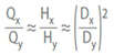
If the diameter reduction is limited so that a mutual overlap of the vanes still remains, the relationship between the flow rate (Q), the head (H) and the impeller diameter (D) of the full-diameter (x) impeller and the corresponding values of the trimmed impeller (y) can be approximately expressed as follows:
The pairs of values Q and H with the indices x and y are situated on a straight line passing through the origin of the Q/H coordinate system.
See Fig. 1 Impeller trimming
Fig. 1 Impeller trimming: Diagram for determining the reduced impeller diameter
While the diameter of low specific speed impellers (up to approx. ns = 25 rpm) can be trimmed considerably without impairing the pump's efficiency impellers of higher specific speeds suffer a notable reduction in efficiency. A similar technique involvess reducing only the impeller vane diameter.
The impeller vanes are vanes or blades in an impeller, which rotate with the pump shaft and in so doing convert the mechanical energy into pump output power.
In-line pumps are centrifugal pumps, whose pump discharge and pump suction nozzles lie in a straight line of piping. It is often used in building services applications (e.g. heating and air conditioning) and is driven by means of a
Canned motor Fig. 1 In-line pump
IEC standardised motor Figs. 2 and 3 In-line pump
Fig. 1 In-line pump: Circulator pump with canned motor and thermal insulation
Fig. 2 In-line pump: Twin-circulator pump with IEC frame motors
Fig. 3 In-line pump: Circulator pump with standardised IEC frame motor
An inclined rotor pump is a pump whose rotor is designed as a disc. See Fig. 1 Inclined rotor pump
This disc is arranged on the drive shaft in an inclined position. It rotates in a cylindrical casing with an axialpump suction nozzle (inlet nozzle) and a radial or tangential pump discharge nozzle. A centrifugal force field which maintains a pulsating flow is generated in the casing filled with fluid.
Inclined rotor pumps are suitable for pumping slurries and pulp-like substances (see Pulp pumping) with special rotors and casings can be designed to also cut solids contained in the fluid handled.
Sediments of natural minerals, such as calcium, magnesium, iron and manganese in the water supply network are called incrustation. This usually results in an increased head loss in a piping.
The inducer's task is to reduce the NPSH required by the pump, which is achieved by increasing the static pressure upstream of the impeller. The vortex flow (pre-swirl in direction of the impeller rotation) downstream of the inducer plays an important role (see Inlet conditions).
See Fig. 1 Inducer
Fig. 1 Inducer: Inducer (illustrated in red) upstream of a submersible borehole pump's first stage
A significant reduction of the required NPSH value using an inducer can only be achieved under low flow conditions. As a result, the operating range of a pump fitted with an inducer is limited when compared with a pump without inducer.
In order to avoid blockage of the flow cross-sections by vapour bubbles (see Cavitation) in the inducer on the vane pressure sides, the inducer should be sized for higher performance than actually required for the desired operating range. It will therefore operate in the low flow range at almost all possible operating points and be able to provide the pump impeller with the required inlet pressure (see Characteristic curve).
Under extreme low flow conditions, low-frequency pressure fluctuations, typical for inducers, can be observed. This is due to cavitation and fluctuating approach flows.
The flow separation on the vane's suction side which may occur under certain circumstances during low flow operation is far less of a problem than flow separation on the vane pressure side, which usually leads to the collapse of the head in the case of axial impellers.
The pump head plays an important part in the evaluation of the efficiency of a pump equipped with an inducer. The inducer operates under conditions of considerable entry shock (see Shock loss in the low flow range) and therefore at a lower efficiency than the pump impeller. The ratio between inducer head and pump impeller head is important as the deterioration of the efficiency of the whole unit, i.e. the inducer and the pump, is highly dependent on this ratio. It follows that the provision of an inducer on pumps with a low specific speed (high head) is less detrimental to efficiency than in the case of high specific speedpumps. Inducers are mainly available in three different vane designs.
Inducer designs
Helical surface: the head is solely generated by the vanes'incidence angles (for inducers with a low head).
Cambered vanes with various types of meridian lines: the head is determined both by incidence and deflection.
S-curved vanes: these shape the path of the flow deflection (see Vortex flow).
Inducers fitted with a small number of vanes (max. four) have achieved good results in practice as they involve only a small risk of blockage by vapour bubbles. As inducers are exposed to very high stresses as a result of cavitation, they are manufactured using cavitation-resistant materials.
Manufacturing methods frequently used for inducers
Welding: preformed sheet steel vanes
NC (numerical control) milling: in accordance with calculated coordinates
Copy milling: in accordance with an accurate model
An inductive displacement sensor is a measuring instrument (also see Sensor) that utilises changes in output voltage when an armature moves in a coil for e.g. indirect displacement/position measurement. It operates like a differential transformer except that it uses only one coil and one moving armature.
An inductive proximity sensor is a measuring instrument (also see Sensor) that utilises changes in a magnetic field for e.g. indirect position measurement.
An inductive sensor is a measuring instrument that utilises changes in electromagnetic induction, e.g. to detect valve disc position (also see Sensor).
To ensure trouble-free operation of a centrifugal pump the approach flow to the impellermust be disturbance-free and uniform.
While energy transfer from the vanes to the fluid handled is based on the centrifugal effect in the case of low specific speed radial flow pumps it is effected via flow deflection at the blades in the case of high specific speed propeller pumps. For this reason, pumps with higher specific speeds are more susceptible to disturbances in the approach flow than those with lower specific speeds.
Depending on the impeller type involved, the conditions for disturbance-free approach flow vary and must be strictly complied with. The three major criteria are absence of swirl, a uniform velocity distribution and absence of vortices
Absence of swirl
The swirl (see Vortex flow) at the impeller inlet represents a disturbance of the ideal approach flow to the impeller, unless it is deliberately used tocontrol the head or improve the pump's suction characteristics (see Inducer) Vortex flows at the inlet cross-section of a pump in most cases are the result of asymmetries in the inlet (transverse approach flows, flows across an elbow, asymmetrical flow separation) or suction recirculation (see Operating behaviour).
If the direction of the tangential components at the pump's inlet cross-section coincides with the pump direction of rotation the swirl rotates in the same direction. As a swirl in the same direction of rotation as that of the pump increases (i.e. larger tangential components of the vortex flow), the head, pump input power and efficiency will decrease at constant flow rate. The reason is the reduced deflection performed by the impeller vanes in comparison with their design point capability.
If a swirl in the opposite direction to the pump's direction of rotation increases, the head will increase at constant flow rate to the point where the vanes are overloaded (flow separation at the suction side of the vane, mechanical vibrations). The pump's efficiency will however drop faster than in the case of a swirl in the same direction of rotation. In the case of a swirl in the opposite direction, the resultant additional pump input power requirement may lead to drive overload.
The disturbance factor "swirl" in the approach flow is established via flow velocity measurements with regard to both magnitude and direction, using probes, hot wire or laser measurement equipment or (as often employed in modelling) a rotameter, i.e. a speed-monitored paddle wheel of the size of an impeller arranged in the suction nozzle.
The swirl can also be established using CFD analysis.
Honeycomb flow straighteners offer the best solution for reducing existing swirl components, but simple diffuser plates in the form of baffles, cruciform flow straighteners and centrally arranged longitudinal baffles (splitters) are also effective. See Fig. 1 to 3 Inlet conditions
Fig. 1 Inlet conditions: Intake chamber upstream of a radial centrifugal pump designed for disturbance-free approach flow to the impeller with central guide baffle (marine pump with inducer)
Fig. 2 Inlet condition: Intake accelerating elbow for disturbance-free approach flow from a 90° change in direction
Fig. 3 Inlet conditions: Intake chamber examples
On the basis of tests on pumps equipped with pre-swirl control (specific speeds ns of 70 to 200 rpm), tangential components of the flow velocity at the suction nozzle's outer edge which amount to less than 7 % of the corresponding axial components do not represent a major disturbance. This corresponds to a swirl angle of approx. 4 degrees.
The percentage rate above must be reduced in the case of pumps with specific speeds exceeding 200 rpm due to the need to comply more strictly with the inlet conditions.
Complete absence of swirl at the pump's inlet is practically impossible to achieve.
Uniform velocity distribution
When designing a pump impeller, a uniform velocity distribution in the cylindrical portion of the suction line is generally assumed. This is understood as comprising all the profiles of the axial flow velocities between the rectangular profile and the profile for fully developed turbulent flow in the pipe.
Distortions of the uniform velocity distribution pattern mainly occur as a result of flow around obstacles (wake depressions), and from any form of flow deviation and separation. See Fig. 2 Intake elbow
The greater the deviation from uniform velocity distribution, the less likely it is that the pump can reach the required performance data as the individual vanes are exposed to an approach flow under low flow and overload conditions in the region of the velocity distortion.
If the non-uniformity of velocity distribution is not rotationally symmetric, mechanical vibrations will occur as a result of the transient flow along the vanes.
Obstacles in the shape of screens or perforated plates arranged uniformly across the flow cross-section, a straight length of piping.
or considerable acceleration via a nozzle of an appropriate length will have a stabilising effect on the distorted velocity distribution.
If such devices cause the NPSH of the system (NPSHa) to drop to an unacceptable level making cavitation more likely, the only effective (but often very expensive) remedy is to improve the hydraulic characteristics of the intake chamber. Widening of the intake space results in lower velocity peaks and lengthening it will reduce the wake depressions. Deflections and flows around obstacles should be avoided or their effects minimised.
Rotationally symmetric deviations of the axial velocity from the volumetric average by more than ± 10 % and non-rotationally symmetric deviations of the local axial velocity on a circular segment by more than ± 5 % are generally considered unacceptable. However, deviations of the order of ± 5 % in the case of pumps with a very high specific speed (ns > 200 rpm) may already prove to be unacceptably high.
Absence of vortices
Vortices develop in shear flows and at locations with high gradients in the velocity profile. They may occur in the approach flow as a result of flow separation, deceleration, acceleration, branching off and a flow around installed structures. A differentiation is made between surface and submerged vortices; a more detailed presentation of different vortices is provided in the classification according to Hecker. Steam and gas may develop in the vortex core at a sufficiently high speed of rotation. See Fig. 4 Inlet conditions
Fig. 4 Inlet conditions: Vortex classification according to Hecker
Vortices which reach as far as the pump inlet impair the pump's performance data and operating behaviour. They include but are not limited to air-entraining surface vortices and air/gas-filled submerged vortices.
Swirl may lead to changes in the power, performance, head and flow rate. The vortices are often transient and, as a result of fluctuating pump performance, may in some cases be a cause of increased vibration and noise values which are associated with mechanical stress on the impeller or impeller vanes. Vortices' air and gas content additionally results in reduced performance data and lower efficiencies.
The most important prerequisite for disturbance-free continuous pump operation is the prevention of air-entraining vortices and air-/gas-laden submerged vortices. For this reason, surface vortices from type 3 and submerged vortices of types 2 and 3 (according to Hecker) are not acceptable for practical applications. Various measures can be taken to prevent air-entraining intake vortices (see Intake chamber).
Measures to be taken to prevent air-entraining vortices
Improving the approach flow to avoid rotation and gradients in the velocity profile
Increasing submergence (h1) See Fig. 3 Inlet conditions
Covering the suction water level vulnerable to air vortices by means of a raft
Installing anti-vortex baffles in the region of suction water levels vulnerable to air vortices
Measures taken to prevent submerged vortices
Improving the approach flow to avoid rotation and gradients in the velocity profile
Using inlet cones with baffles see Fig. 1 Intake chamber
Influencing the flow close to the respective walls by fitting anti-vortex vanes or similar structures
Standardised intake elbows and chambers optimised in model tests offer the best conditions for an approach flow that is as uniform and vortex-free as possible. See Fig. 3 Inlet conditions
In the case of pumps installed in pipes, the inlet line upstream of the pump should not have any turbulence-inducing structures. Elbows, valves and pipe branches may cause unacceptable inlet flow conditions for the pump. Several elbows installed one after another and/or elbows installed asymmetrically must be avoided. An unfavourable arrangement of these components may severely affect the pump's operating behaviour.
In the case of double-entry pumps, it is important to pay particular attention to the inlet conditions. When the flow leaving the elbow is asymmetrical (resulting from elbows installed asymmetrically), the impeller halves are not uniformly subjected to load, i.e. the impeller halves operate at different load points. In such cases, the negative impact on the NPSH value of the pump (NPSHr), the vibration behaviour and the load on the bearings may be much more pronounced than the effect on the pump characteristic curve.
If sources of interference upstream of the pump cannot be avoided in the system, it is necessary to stabilise the inlet flow to an acceptable level.
This can be achieved by installing a sufficiently long, straight length of piping (approx. 5 to 8 times the nominal diameter DNs between the pump and the point of interference), elbows with a large radius, elbows with deflection vanes See Fig. 3 Inlet elbow and acceleration nozzles.
Disturbance-free approach flow examples
The intake chamber design for a marine pump with inducer provides a relatively wide and long intake (deflection at low flow velocity). It is additionally equipped with a longitudinal baffle (splitter) to prevent larger swirl components. See Fig.1 Inlet conditions
Disturbance-free inlet flow in an intake elbow with circular cross-sections can be achieved if in the 90° deflection zone (elbow) the flow velocity is increased to approx. 2 to 4 times the pipe flow See Fig. 2 Inlet conditions . Accelerating elbows of this type are also successfully manufactured from concrete with adapter cross-sections from rectangular shapes to circles. See Fig. 6 Cooling water pump
Recommended intake chamber designs for disturbance-free approach flows to vertical pumps are shown in Fig. 3 Inlet conditions. The covered intake chamber with inlet cone and splitter also allows cross flows to the pump, e.g. emergency operation in the event of a failure of associated travelling screens.
An inlet cone is a flow deflecting device anchored in the intake chamber floor immediately upstream of the bellmouth. In order to prevent rotation of the flow around the inlet cone (see Inlet conditions) radial baffles are often integrated into the inlet cone casting.
The pump's inlet cross-section is usually deemed to be the flow cross-section of the pump suction nozzle. If there is no suction nozzle the inlet cross-section must be defined as a suction-side flow cross-section (e.g. of a tank, a pipe) with known geodetic and hydraulic data (see NPSH). Refer to DIN EN ISO 17769-1 for examples.
Inspection is a form of checking that employs various measures for the purpose of identifying and assessing the actual condition of a system's technical resources in accordance with DIN 31051.
The following aspects are checked as part of a centrifugal pump inspection:
For centrifugal pumps, "installation" encompasses the arrangement of the pump set on site, together with all piping connections necessary for commissioning. The pump set must be installed so that all external forces and moments (see Pump nozzle load) are safely carried by the foundation, supports, frames, plates or by the piping.
The type of installation depends on the pump type and frequently on the application: installation on a foundation or without foundation, wet well or dry installation, indoor or outdoor installation.
Installation on a foundation
In the case of an installation on a foundation (see Pump foundation) it is necessary to distinguish between horizontal and vertical shaft pumps.
Established designs for centrifugal pumps installed horizontally are the back pull-out design and for drive ratings of up to 50 kW the closed-coupled design (see Close-coupled pump). With the exception of close-coupled pumps, horizontal pumps and drives are supplied mounted on common baseplates. In the case of large pump sets and pump sets with gear units or booster pumps individual baseplates are used for the components.
These baseplates are placed on the foundation and the cavities between them are filled with grout, e.g. cement mortar. The foundation bolts should only be tightened after the grout has set. Grouting provides the baseplates with the rigidity needed to prevent undue deformation or warping under load (e.g. pipeline forces).
After grouting, the couplings of the various pump set components are aligned by placing shims under the feet of the machines. After adaptation and connection of the piping to the pump (avoiding transmission of any stresses or strains onto the pump), and after installation of the accessories (e.g. lubricating device, filter, lubricating oil pump, valve etc.) an alignment check completes the installation of the pump set.
A V-belt drive is often used for horizontally installed pumps with single-vane or diagonal impeller (see Impeller). A V-belt drive with solid pulleys is suitable for minimising surge pressures in the system.
Instead of a belt drive it is also possible to employ a variable frequency electric motor. The use of standardised electric motors makes operation at any pump speed possible (see Rotational speed) and allows the pump's output to be easily matched to the required performance data at maximum impeller diameters. An optimal hydraulic selection of the waste water pump with regard to its efficiency and NPSH can therefore be guaranteed.
The installation of vertical pumps and drives roughly corresponds to that of horizontal pumps. However, there is no need to align the couplings if the pump and drive are connected to each other via a motor stool. In these cases, the pump set is mounted onto the foundation via a foot flange. The motor stool determines the drive's exact position.
Installation without foundation
Installation without a foundation is chosen if the weights of the pump sets to be installed and the anticipated loads by the piping are limited, if the pump must remain transportable, or if vibration dampening is to be provided to ensure that solid-borne noise is not transmitted to the floor.
Submersible motor pumps, most in-line pumps and glandless pumps (e.g. circulating pump) are installed without afoundation. Large units are sometimes supported via additional simple foundations. If this is not the case, baseplates must be designed which are rigid enough to keep deformation within acceptable limits.
Transportable pumps such as fire-fighting pumps or mobile pipeline pumps are attached directly, or via their baseplate, to the mobile frame (e.g. carriage or skid). This type of installation requires flexible piping.
Portable pumps (e.g. garden pumps, cellar/basement drainage or dewatering pumps) are designed as close-coupled pumps which require no coupling alignment. They require no foundation as they are always small pumps attached to flexible hoses and not to a fixed piping. The motor housing and pump casing are designed for placing them on any even and firm surface.
Installation on a baseplate without foundation is sometimes specified for acid pumps to enable the straightforward removal of aggressive leakage fluids from underneath the baseplate. Such baseplates must be designed to be rigid enough to keep deformation within acceptable limits.
Wet well installation
An installation is termed wet well if the outside of the pump casingis in contact with the fluid handled. The advantage of wet well installation is that the installation and structural building costs are lower. The pump is submerged directly in the fluid handled, e.g. in the case of submersible pumps (see Deep-well turbine pump), submersible motor pumps or most tubular casing pumps. The installation types of tubular casing pumps are further subdivided into those where the weights of the pump and the motor are carried either by a common floor level or by different floor levels of the structure and whether the discharge line can be installed either above or below the floor level of the pump sump.
Dry installation
If the pump casingremains dry on the outside, the pump is said to be dry-installed. The advantage of this installation is the fact that the pump room is accessible, which allows regular outside pump inspection (e.g. at the shaft seal) and the installation of other machinery.
This applies to most vertical marine pumps, whether pedestal-mounted (with the pump foot attached to a steel frame on the engine room floor, and with the pump casing and motor housing connected to one another by a motor stool) or bulkhead-mounted (the motor stool is attached to a bulkhead of the engine room).
The installation of a pump set with no protective building or roof is referred to as outdoor installation. General requirements for outdoor installation do not exist as the conditions depend very much on the place of installation.
The intake chamber is often referred to as a pump sump. It is a collecting chamber situated directly upstream of a centrifugal pump through which the fluid handled, usually water, flows towards the pump. This ensures that the approach flow towards the centrifugal pump is evenly balanced on all sides and free of turbulence (see Inlet conditions). Such a smooth, disturbance-free approach flow is indispensable for high specific speed tubular casing pumps with propellers or mixed flow impellers because these pumps respond immediately to irregularities and disturbances in the approach flow. A simple intake chamber design is all that is required to avoid damage from cavitation and vibrations, and a possible drop in pump power output or pump efficiency caused by irregular approach flows. The risk of air-entraining vortices being sucked in from the water surface is avoided by ensuring that water levels in the intake chamber are sufficient. The required excavation depth depends on the intake chamber's design and shape. See Fig. 1 Intake chamber
Fig. 1 Intake chamber: Four different intake chamber designs
Intake chambers have a simple structural shape with a rectangular floor plan. A comparison of the four different intake chamber designs reveals that, given an identical flow rate, design variant I requires the highest minimum water level, variant IV the lowest. The designs I, II and III are open intake chambers suitable for axially parallel approach flow. Design variant IV with a splitter is also suitable for perpendicular approach flow. In the case of complex inlet conditions, model tests are advisable.
A disturbance-free approach flow can also be achieved using intake elbows. Economic efficiency should be calculated when deciding whether an intake chamber should be provided. They are often built for vertical cooling water pumps.
In power stations, operational reliability is of crucial importance for pump availability. The intake chamber therefore represents a structural unit which must be designed and built with great care.
Intake chambers are also employed in irrigation and drainage stations where simple designs can significantly reduce construction costs
The intake elbow, also referred to as the suction elbow, serves to direct the fluid flow to the pump, usually a volute casing pump via a 90º bend. The intake elbows employed are usually cast or welded standard elbows with constant cross-sections. A drawback of these elbows is that they cannot ensure a regular, disturbance-free flow (see Inlet conditions) downstream of their outlet, which is however required by high specific speed pump impellers. In this case, accelerating elbows are a suitable option. They provide regular flow profiles at their outlet as the fluid's flow velocity is doubled in the deflection zone. See Fig. 1 Intake elbow
Fig. 1 Intake elbow: Accelerating elbow upstream of a high specific speed volute casing pump
The intake elbows for large vertical tubular casing pumps are generally made of concrete with wooden formwork or permanent sheet steel formwork. In the first section of the intake elbow (intake funnel), the flow velocity is increased to two to four times its value at the entry. In the deflection zone immediately downstream, it is increased again to two to four times its value immediately upstream of the bend. The strong accelerations have a balancing effect on distorted velocity profiles which develop due to disturbances upstream of the intake elbow. See Fig. 2 Intake elbow and Fig. 6 Cooling water pump
Another problem arises with double-entry, single-stage pumps (See Fig. 1Pipeline pump), fitted with standard elbows. Due to the distortion of the flow profile downstream of a standard elbow, each half of the impeller receives a different type of flow. This may lead to efficiency losses and cavitation or impair the smooth runningof the pump. This problem can be avoided by installing an acceleration elbow or by employing a compact elbow design with multiple deflection vanes. See Fig. 3 Intake elbow
Fig. 3 Intake elbow: Intake elbow with multiple deflection vanes upstream of a double-suction horizontal volute casing pump (top view)
The integral motor is also referred to as an integral drive or "intelligent" drive and is a three-phase asynchronous motor with integrated frequency inverter for continuously variable speed control.
This means that an integral motor is a compact drive system for pumps consisting of a motor (electrical machine), a power-adjusting element (frequency inverter) and a microprocessor for open-loop and closed-loop control purposes. See Fig. 1 Integral motor
Fig. 1 Integral motor: Compact drive system with motor, frequency inverter and microprocessor (process view)
Some solutions involve permanently integrating the frequency inverter in the motor, while others allow different makes of motor to be used. The latter offer greater flexibility and can, for example, be retrofitted in installed pump systems. See Fig. 2 Integral motor
Fig. 2 Integral motor: Mounted on a vertical pump
Motor-mounted or integrated centrifugal pump frequency inverters have key benefits as compared to separately installed solutions. For example, there is no need for components such as the motor protection switch, wiring, overload or time relay, and expensive shielded cables from the frequency inverter to the motor terminal box. See Fig. 3 Integral motor
Fig. 3 Integral motor: Comparison of initial investment costs of variable speed integral motor and variable speed drive with separate frequency inverter
This, in turn, minimises the electrical load placed on the motor and leads to fewer electromagnetic compatibility (EMC) issues. The closed-loop control system is integrated and eliminates the need for an external device.
EMC filters integrated in the drive improve operating reliability as does the built-in pump and motor protection equipment. All functions required for safe and reliable operation of the centrifugal pump are thus already incorporated.
Interest calculation is a mathematical process that is applied once a year or more for the purpose of working out the interest (also see Economic efficiency).
Interfaces as they apply to electrical engineering and automation describe the connection point shared by two assemblies, devices, or communications systems.
The unit on one side of the interface is connected to the one on the other side via interface cables, which are used to exchange data and control signals.
The type of data transmissionin question dictates whether parallel (IEEE 488) or serial (RS232, RS485) interfaces are required with respect to transmission speeds and distances.
Interference immunity describes the ability of a device, apparatus, plant, or system to operate in an electromagnetic environment in a satisfactory manner, without being disturbed by the electromagnetic fields. Electromagnetic compatibilityor EMC, can be used to quantify interference immunity.
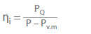
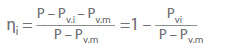
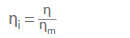
Efficiency scale-ups usually relate to internal efficiencies. These can also be determined on the basis of an analysis of the internal losses (PL.i) of the centrifugal pump (see Head).
The power loss (PL.i) comprises:
Losses incurred on the flow path of the fluid through the impeller,diffuserand pump casing i.e. internal fluid friction, wall friction, momentum exchange losses and shock losses
Losses incurred as a result of disc friction, friction at the throttling rings and cylindrical surfaces at the impeller outlet
Losses caused by internal circulation flows, in particular the secondary flows from the impeller discharge side through the clearance gap to the impeller suction side, or from the vane pressure side to the vane suction side through the impeller gap (see Clearance gap loss) and reverse flows resulting from flow separation and low flow operation
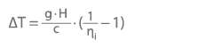
All internal losses cause the fluid handled to heat up, resulting in a temperature difference (ΔT). The heat radiation through the pump casing can be ignored in this context.
g Acceleration due to gravity in m/s² H Head in m c Specific heat capacity in J ∙ (kg · K)-1 ΔT Temperature difference in K or °C
If the fluid is transported through the pump several times in succession as is the case in test facility circuits (see Pump test facility) the useful power output converted into heat in the circuit (e.g. in the throttling element or in the piping) is added to the heat developed inside the pump from one cycle to the next, meaning that cooling may be required.
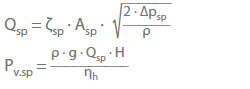
Due to the difference in pressure upstream and downstream of the impeller (see Clearance gap pressure) part of the fluid handled that already has a highestatic pressureflows back through the clearance between the stationary and rotating components of the pump (clearance flow).
The equations below are used to calculate the clearance flow (Qcl) and the power loss due to internal leakage (PL.cl):
ζcl Clearance flow coefficient Acl Clearance gap area Δpcl Difference in static pressure upstream and downstream of the clearance gap g Acceleration due to gravity ρ Density of the fluid handled ηh Hydraulic efficiency H Head
The power loss due to internal leakage is influenced by theReynolds numberof the clearance flow, the surface roughness and the geometry of the clearance gap.
The power loss due to internal leakage (PL.cl) referred to the power input (P) for geometrically similar pumps with geometrically similar clearance gaps is independent of the pump size and the circumferential speed, but significantly dependent on the specific speed (ns).
As shown in the graph for a simple cylindrical clearance gap at the impeller inlet with a relative clearance gap width (s/Dcl) of 0.002 and a relative casing wear ring width (b/Dcl) of 0.133, the internal leakage loss at specific speeds of ns > 20 rpm is negligible. See Fig. 1 Clearance gap loss
Fig. 1 Internal leakage loss: Power loss due to internal leakage, divided by power input, as a function of specific speed of pumps with radial impellers, plotted here for a smooth-surface cylindrical clearance gap of s/Dcl = 0.002 and b/Dcl = 0.133
For specific speeds of ns < 20 rpm, a complicated and expensive reduction of the internal leakage losses is worthwhile, e.g. by narrowing the clearance gap. The reduction in internal leakage losses is almost linear in relation to the decrease in gap width. See Fig. 2 Internal leakage loss
Fig. 2 Internal leakage loss: Power loss due to internal leakage, divided by the power input of a volute casing pump with a specific speed of ns = 20 rpm and a smooth-surface cylindrical clearance gap of b/Dcl = 0.133, plotted as a function of relative clearance gap width
By using clearance surface types such as circumferential grooves, honeycomb and cellular surfaces, it is possible to minimise internal leakage losses in centrifugal pumps. This, however, reduces the centring restoring force of the clearance essential for smooth operation (Lomakin effect).
The internal rotor motor is a direct current motor whose rotor is internal and the stator external. The external rotor motor has the opposite design and is encountered less frequently.
Invested capital is the amount of money that needs to be provided in order, for example, to put centrifugal pumps into service (also see Economic efficiency).
Irrigation pumps are used to pump water from a lower to a higher level from which the water then flows through channels to the fields requiring irrigation (lift operation) or to raise it to the required pressure head so that it can be sprayed on the fields via piping systems (sprinkling). The heads involved range from approx. 1 m for normal lift operation to 40 m for sprinkling. In special cases, heads exceeding 100 m may be required.
The flow rate varies according to the area to be irrigated, the nature of the soil, the type of crop cultivated and the climate. A quantity of 1 to 2 litres per second and hectare can be assumed as a rough value for orientation.
Tubular casing pumps with submersible motors See Fig. 1 Irrigation pump
Fig. 1 Irrigation pump: Maintenance-free propeller pump with submersible motor and adjustable blades (cf. Fig. 2 Pump for use in low-lift pumping station)
Suitable pump types for heads above 10 m
Tubular casing pumps with mixed flow impellers See Fig. 2 Irrigation pump
The isolating transformer typically transfers an alternating voltage 1:1 via two electrically isolated coils and is used to provide a voltage not connected to the earth potential, for example.
")
")
 (shown with front shroud removed)")
")
")
 Closed, single-entry impeller b) Open, single-entry impeller c) Closed, double-entry impeller")
")

")
")

")


")
 impeller arrangement a) Single-stage b) Two-stage c) Six-stage")
 Double-entry, single-stage b) Four-entry, single-stage c) Double-entry, three-stage")
 Two-stage (back-to-back) b) Four-stage (crossover) c) Six-stage (back-to-back)")


 upstream of a submersible borehole pump's first stage")
")


")
")


")
