A feed funnel valve is employed for smaller pumps with foot valves to manually vent the suction line and pump prior to start-up so that suction line and pump can be filled with the fluid handled (also see Priming).
A feedback value transmitter is a sensor, that converts the control variable into a standard electric signal for closed-loop control in compliance with DIN 1319.
The field bus is a bus system that is used for communicating in automation systems to enable the direct connection of control equipment and fielddevices (e.g.sensoren, actuators) and the transmission of data in real time. To this end, small quantities of data are transmitted digitally betweenthe sensors, actuators, and control equipment on the bus.
The field level is also referred to as the sensor or actuator level and represents the lowest level of the automation pyramid in industrial production systems. Field levels are in place to quickly collect basic data in the form of binary signals. See Fig. 1 Field level
Fig. 1 Field level: Example of an automation pyramid
Each level transitions fluidly to the next and is responsible for carrying out specific tasks, for which special methods of analog and digital data transmission and processing have been developed.
Centrifugal pumps and valves are located at field level and are therefore considered field devices, or intelligent field devices, depending on the extent to which electronics have been integrated (see Communications system).
Filters are found in many different fields. For example, in electronics they are electrical circuits for attenuating certain frequencies from a signal, and in fluid systems they are devices for separating media (also see Valve /strainer).
A fire-fighting pump is a centrifugal pump which is used for pumping fire-fighting water. Fire-fighting pumps can be designed for transportable use (e.g. on fire-fighting vehicles or as portable fire pumps) or for stationary use (e.g. hydrants, sprinkler systems).
Transportable fire-fighting pump
Transportable fire-fighting pumps are single-stage or multistage single-entry centrifugal pumps. Transportable fire-fighting pumps are self-priming (see Self-priming pump). They are of compact, light-weight design. See Fig. 1 Fire-fighting pump
Fig. 1 Fire-fighting pump: Mobile fire-fighting pump (portable fire pump with water ring pump for venting)
The sizes and operating data of fire-fighting pumps are standardised to EN 1147, EN 14466 and EN 1028-1; the corresponding suction and discharge hoses are standardised to DIN 14810, and the couplings to DIN 14811. The pressure losses in the hoses correspond approximately to the pipe friction losses in plastic piping. The drive is usually a combustion engine, allowing the speed to be simply controlled via the fuel supply. In practice, the flow rates and heads can vary widely (see Throw).
Transportable fire-fighting pumps are either installed on fire-fighting vehicles as integrated or front-mounted pumps, or they are used as portable fire pumps. Portable fire pumps consist of a pump end flanged to a motor. This assembly is mounted on a protective frame. Some modern portable fire pumps (which exceed the standards in size) are driven by a gas turbine, which not only allows universal fuel selection but also increases the output and decreases the weight. For weight reasons the protective frame often consists of two separate parts, which allows the pump end to be quickly and easily separated from the drive end. Pumps which are mounted on fire-fighting vehicles are driven by the vehicle's motor via a jackshaft.
Fire-fighting pumps are usually in idle state. They are only operated for testing water / water mist systems (to PREN 14972) or foam systems (to EN 13565), and in the event of fire. This is why reliable start-up and fast ramp-up to full pump power output (also after prolonged standstill) is of particular importance.
Applicable regulations are issued by fire insurance companies and associations such as VdS Schadensverhütung, Factory Mutual, National Fire Protection Association, APSAD/CNPP and LPCB.
Stationary fire-fighting pump
The most important and most common fire-fighting systems are sprinkler systems. Sprinkler systems consist of several sprinkler heads which are connected via a piping system. Large heat automatically triggers the sprinkler heads in defined intervals to protect the rooms they are installed in. Sprinkler systems are automatic fire-fighting systems.
Fire hydrants are another type of fire-fighting system. Hydrants are activated manually. Depending on their type they are either designed for general use or for activation by fire-fighters only.
Wet-pipe sprinkler systems are the most common type of sprinkler system. In this system, the pipelines are permanently under pressure and filled with water. The fire-fighting water will be discharged immediately as soon as one or several sprinklers have been activated. In dry-pipe sprinkler systems pipelines laid in areas which are likely to be effected by frost/freezing are filled with air.
Depending on the hazard class, sprinkler systems may be required to be supplied with water from two independent sources, using either one or two fire-fighting pumps. If two pumps are used, two independent energy sources may have to be provided, depending on the applicable regulations.
Fire-fighting pumps can be driven by an electric motor or a combustion engine. See Fig. 2 Fire-fighting pump
Fig. 2 Fire-fighting pump: Stationary unit with combustion engine
To ensure that stationary fire-fighting pumps start up reliably for testing the fire-fighting system or in the event of fire, stationary fire-fighting pumps are designed in compliance with the relevant regulations such as VDS CEA 4100 and subjected to a type test by an independent certifier.
Firmware refers to a microprogram that the manufacturer implements as hardware-specific software in the memory chips (microcontrollers) of electronic devices to control overall device functionality.
Fittings in a centrifugal pump system comprise all piping components which function to change the piping's direction, to install piping branches, and/or to provide a transition between different pipe cross-sections.
Fittings should be shaped to offer the least possible resistance to flow in order to minimise pressure losses (see system head) where this involves increased manufacturing costs, these should be weighed against the corresponding gains in economic efficiency.
Common fittings:
Pipe bends
Pipe bends should have a radius of curvature of R > 2 · D + 100 mm (D = pipe diameter) particularly if they are fitted immediately upstream of pump suction nozzles. Pipe bends fabricated from cylindrical segments welded together should consist of at least six segments for a 90° bend. See Fig. 1 Fitting
Fig. 1 Fitting: 90° pipe bend
Y-branch
Y-branches' fluid dynamic characteristics make them preferable to tees. See Fig. 2 Fitting
Fig. 2 Fitting: Y-branch
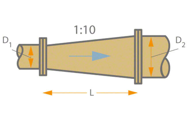
Diffusor
Its face-to-face length (L) should be approximately L = 5 ∙ (D2 – D1) (D = pipe diameter) when used as a diffuser in flow direction. Diffuser outlets (e.g. in the case of low-lift pumping stations and pumps for use in low-lift pumping stations should be sized such that the discharge velocity (v) (see Flow velocity) is 1.0 to 1.5 m/s. See Fig. 3 Fitting
Nozzle-shaped reducer
In contrast to a diffuser, the face-to-face length of a fitting used as a reducer can be much shorter. A nozzle-shaped reducer features favourable flow characteristics. See Fig. 4 Fitting
Fig. 4 Fitting: Nozzle-shaped reducer
Reducer for avoiding air pockets
Eccentric reducers should be installed in horizontal suction lines to avoid the formation of air pockets (see Formation of air pockets). See Fig. 5 Fitting
Fig. 5 Fitting: Reducer for avoiding air pockets
Branch fitting for avoiding air pockets
Eccentric branch fittings should be installed in horizontal suction lines to avoid the formation of air pockets. See Fig. 6 Fitting
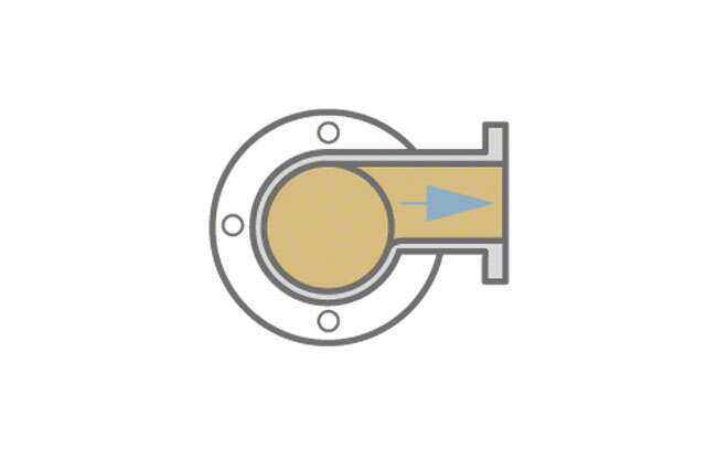
Flanges are used in piping construction to connect two pipe sections to one another, or to connect pipe sections to apparatus casings, valve bodies or machinery casings (e.g. of pumps).
In mechanical engineering, flanges are also employed as transmission elements (e.g. flange couplings on drive shafts). In terms of form, function and materials used, flange designs (e.g. on pump casings) are always based on established flange standards. Only in exceptional cases (e.g. for pressures above 400 bar) are standards unavailable.
A flange standard lays down the dimensions, surface finish, facing type, marking, material and technical specifications for flanges.
National flange standards in Europe have largely been superseded by the European EN 1092 series. It comprises flanges with DIN origin and PN/DN designations (DN classification being dependent on PN). Various national standards bodies have incorporated this standard into their respective national standards: DIN EN 1092; BS EN 1092 und NF EN 1092.
European standard EN 1092: Flanges and Their Joints (Circular Flanges for Pipes, Valves, Fittings and Accessories, PN designated)
Part 1: Steel flanges, PN 2.5 to PN 400
Part 2: Cast iron flanges, PN 2.5 to PN 63
Part 3: Copper alloy flanges, PN 6 to PN 40
Part 4: Aluminium alloy flanges, PN 10 to PN 63
British standards for flanges
BS EN 1092-1 (Cast steel flanges) for nominal pressures, see DIN EN 1092-1
BS EN 1092-2 (Cast iron flanges) for nominal pressures, see DIN EN 1092-2
A further European flange standard is EN 1759. This standard only features ANSI/ASME flanges (ASME B 16.5 2020 edition) with Class and NPS designations.
American standards for flanges
ASME B 16.1: Gray iron pipe flanges and flanged fittings (cast iron flanges, Classes 25, 125 and 250)
ASME B 16.5: Pipe flanges and flanged fittings: NPS 1/2 through NPS 24 Metric/Inch Standard; (Cast steel and weld-neck flanges Classes 150, 300, 400, 600, 900, 1500 and 2500)
In the EN 1092 standard, the numerical value in the PN designation is equal to the max. applicable pressure in bar at a reference temperature of 20 °C.
Class figure in American flange standards
For cast iron flanges, the figure in the Class designation is equal to the max. applicable pressure in psi at temperatures ranging from 66 to 232 °C depending on the class.
For steel and cast steel flanges, the figure in the class designation is equal to the max. applicable pressure in psi at temperatures ranging from 350 to 650 °C depending on the material.
At a temperature of 20 °C, the figure for the max. applicable pressure is therefore considerably higher than that designating the class, especially for steel and cast steel flanges. Although PN designations are not used in American flange standards, they are matched with their equivalent pressure classes in ASME B 16.5-2020.
Flanges to ISO 7005 are internationally standardised. This standard series comprises DIN flanges (PN 2.5; 6; 10; 16; 25 and 40) and ASME flanges. This standard, however, also specifies DN and PN designations for ASME flanges (PN 20; 50; 110; 150; 250 and 420).
Flange types may vary significantly depending on the application. The faces of flanges used with non-positively seated sealing elements are flat or of a raised face, spigot and recess or tongue and groove design. A further variant is the O-ring recess and O-ring groove face type.
In the case of positively seated sealing elements, there is a choice of flanges for diaphragm-weld packings to DIN 2695 with chamfer or a smaller raised face diameter and lens-shaped gaskets to DIN 2696 with machined recess.
The different sealing element types, dimensions, design features and materials are not covered by the European standard EN 1092 (see Flange standard).
The sealing element dimensions are specified in the EN 1514 standard series. See Fig.1 Flange type
Fig. 1 Flange type: Flange facings
Flange types classified by application
Plate flange for soldering or welding
Loose plate flange
Blind flange
Welding neck flange
Hubbed slip-on flange for welding
Threaded flange
Integrally cast flange (flange forming an integral part of a casing or fitting)
A flanged motor pump is an alternative to a close-coupled pump, It is installed on motor feet rather than pump feet. A flanged motor pump can absorb larger pipeline forces and moments than a close-coupled pump. As a result, it is able to transfer larger amounts of hydraulic power.
The flat belt drive is a belt drive, characterised by the fact that its belt is flat. The belt can be made from leather, plastic, or rubber and does not require lateral guidance when travelling over crowned belt pulleys.
The float switch is a measuring instrument (also see Sensor), that automatically controls the fill level of a tank to provide dry running protection for a submersible motor pump, for example.
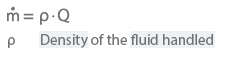
Flow through a section is a variable used to measure the quantity of a flowing fluid. A distinction is made between volume flow (volume flow rate) and mass flow (gravimetric analysis).
The flow coefficient (φ) is a dimensionless quantity used to describe the volume flow rate. It is also referred to as the volume or volume flow coefficient and characterises the flow rate (Q).
New Content Item (1)
When the flow rate varies at constant rotational pump speed, vm ~ Q and therefore φ ~ Q.
The flow coefficient (φ) is therefore indicative of the abscissa (analogous to Q) on H/Q curves plotted in non-dimensional representation. With reference to the vane inlet and outlet diameters, the following equations are obtained:
New Content Item (1)
With regard to the head coefficient, it is preferable to adopt the flow coefficient related to the impeller outlet.
In pump engineering, flow controllers, often also referred to as flow monitors, serve to monitor and control cooling or lubricating flows through product-lubricated plain bearings, mechanical seals and, frequently, glandless chemical pumps. When a certain, specified volume flow rate is either exceeded or undershot, the flow controller triggers an appropriate switching event (i.e., activation of an alarm or stopping of the pump). The most familiar types of flow controller operate either according to the variable-area or rotameter principle, or according to the dynamic-pressure or differential-pressure principle.
Variable-area principle
In a vertical tube with an upwardly widening taper, a float is exposed to a rising flow of fluid. Exposed to an increasing rate of flow, the float rises until it reaches a specified height at which the switching event is triggered by either a magnet or an inductive sensor.
See Fig. 1 Flow Controller
Fig. 1 Flow controller: Variable-area principle
Dynamic-pressure principle
Here, a flow-induced force acting on a target or plate suspended in a tube is counterbalanced by a spring. If the system is forced out of equilibrium by a change in flow rate, a switching event is triggered. See Fig. 2 Flow controller
A difference in pressure caused by a nozzle or orifice plate in a fluid-conducting tube is converted to a force in a differential-pressure measuring instrument (Barton cell). The ensuing force is counterbalanced by springs. Any change in the rate of flow through the tube forces the system out of equilibrium, hence triggering a switching event. See Fig. 3 Flow controller
The term flow line denotes the circular projection of a stream line in the meridional section plane of an impeller. Rotating this flow line about the axis of rotation creates the so-called flow surface which is important for centrifugal pump impeller calculation (see Flow profile).
Flow measurement refers to the process of quantifying the flow of a fluid as it travels through a section of piping for monitoring (e.g. determining the flow rate) and control (e.g. restricting the flow rate) purposes (also see Metrology).
Recently, optical methods have also been introduced for measuring particle speed as well as Laser Doppler Velocimetry (LDV) and Particle Image Velocimetry (PIV).
Magnetic-Inductive Flow Measurement (MIF)
This is a system that is based on Faraday's Law and does not require throttling or moving components. See Fig. 1 Flow measurement
Fig. 1 Flow measurement: MID measuring principle
The MIF method requires a minimum electrical conductivity of approximately 20 μS/cm for the measured fluid. Regular tap water has an electrical conductivity of 400 μS/cm, whereby 1 S (Siemens) quantifies the conductivity of a conductor with an electrical resistance of 1 (Ohm).
The measurement is carried out by applying an alternating magnetic field to the cross-sectional test area of the liquid. This allows a voltage to be induced at the measuring electrodes (3) that is directly proportionate to the velocity (v) at a given geometry (D) and to the flow rate (Q), if the cross-section is known.
Since this method is virtually independent of the flow profile, significantly shorter upstream and downstream stabilisation distances than with a throttling device (e.g. standard orifice, standard nozzle) can be chosen while achieving the same level of system accuracy.
Ultrasonic flow measurement
The ultrasonic flow measurement system can be fixed to the outside of a piping section and does not require direct access to the liquid.
The transit time difference method is typically applied to measure the velocity of a fluid. See Fig. 2 Flow measurement
The properties of the liquid can vary greatly. Bubbles, solids, or high viscosity can skew measurement results, however.
The doppler method, with the same sensor arrangement, is the better choice if the fluid contains solids.
Pitot tube sensors
Pitot-static tubes such as the Prandtl tube are the preferred means of measuring localised velocity in a flow. See Fig. 3 Flow measurement
Fig. 3 Flow measurement: Prandtl tube (Pitot-static tube); basic principle of a U-tube pressure gauge
Static and total pressure sensors such as the pitot tube utilise the correlation between static and dynamic pressure in a steady-state flow as defined by Bernoulli's equation.
The direction field of a flow is measured using direction-sensitive cylindrical, conical, or wedge-shaped flow sensors or can be determined via tufts, the most basic and graphic directional indicators, if accuracy requirements are not quite as high.
Flow monitors are used to protect pumps from overheating when they are not delivering fluids. Brief periods during which the limit value set is undershot, such as when a pump is being started or stopped, are not critical, however, and are not regarded here.
Different types of response can be chosen to maintain operation of the system, as required by the primary objective of the safety concept.
The flow profile, also referred to as the vane profile, results from the intersection of the flow surface (seeFlow line) with the vane(e.g. vane of an impeller or diffuser or a hydraulically ineffective vane supporting a pump bearing).
The flow profile is generated by adding the vane thickness equally on either side along the length of the median line, according to a specified distribution (e.g. NACA profiles). See Fig. 1Vane cascade
The progression pattern of the profile thickness can be obtained from a table of profiles or it can be calculated according to analytical functions.
This calculation plays an important role, especially with modern NC (Numerical Control) methods.
The vane profile of an impeller is to a large extent dependent on the type of centrifugal pump involved (see Specific speed). Radial impellers and most diffusers almost always have long thin vanes which do not exhibit a distinctive profile. Vane thickness (except for propeller blades) is primarily governed by strength calculation and manufacturing method (e.g. casting, milling, welding, forging, plastic injection) considerations.
In the case of axial propeller blades, flow profiles with a specified thickness distribution and camber dominate. (See also Strouhal number).
Slim profile shapes with the maximum thickness far behind the leading edge (laminar profiles) exhibit favourable characteristics with regard to the NPSHr value and the hydraulic efficiency at the pump's design point.
Thick profiles are less sensitive to approach flow under shock (see Shock loss).
Flow profiles are calculated using singularity methods (imposition of sinks, sources and vortices), for example, and, to an increasing extent, CFD (computational fluid dynamics) methods (see Aerofoil theory).
The flow rate (Q) of a centrifugal pump is the useful volume flow delivered by the pump via its outlet cross-section (see Pump discharge nozzle). Volume flow rates which are tapped upstream of the pump's outlet cross-section for other purposes (e.g. bypass) must be taken into account when calculating the pump's flow rate.
If the fluid handled is compressible, a conversion must be made based on the condition prevailing in the pump suction nozzle the arithmetic mean (Qs+ Qd)/2 may have to be applied.
The unit of the flow rate is m3/s; in centrifugal pump engineering the units m3/h and l/sare more common. Various measuring methods are used for flow rate measurement (see Flow velocity measurement). Various types of flow rate are distinguished in conjunction with the H/Q curve (see Characteristic curve).
Flow rates and their significance
Flow rate at BEP (Qopt): flow rate at the best efficiency point at the rotational speed and for the fluid handled specified in the supply contract
Nominal flow rate (QN): flow rate for which the pump has been designed
Supply contract flow rate (Qcontract): the flow rate agreed in the supply contract (order confirmation)
Minimum flow rate (Qmin): minimum permissible flow rate at which the pump can be continuously operated without suffering any damage at the rotational speed and with the fluid specified in the supply contract
Maximum flow rate (Qmax): maximum permissible flow rate at which the pump can be continuously operated without suffering any damage at the rotational speed and with the fluid specified in the supply contract
Outlet volume flow rate (Qa): volume flow leaving the system's outlet cross-section. See Fig. 2 Head
Occasionally, a so-called pump flow rate (Q/Qopt) and a system flow rate (Q/Qcontract) are defined, where Qcontract is the flow rate specified in the supply contract.
Flow resistance is the force opposing motion and flow of the fluid handled. It is caused by the friction and deflection forces generated as the fluid flows through pipes and valves and results in a pressure drop (see Head loss).
In aero- and hydrodynamics flow separation describes a flow condition in which the flow becomes detached from the wall. If excessive deceleration of the flow occurs (pressure increase), or if there is an abrupt change in the direction of the wall, the flow outside the boundary layer will no longer follow the direction of the wall but will become detached from it. Downstream of the point of separation, the boundary layer thickness increases considerably and local recirculation develops in the resulting dead water zones or areas of separation. Flow separation is associated with eddies and vortices and resultant flow losses.
Flow velocity is the velocity of a defined movement of a fluid in a given space and, in the case of transient flow, as a function of time. The averaged flow velocity in a pipe, for example, is the flow velocity in a cross-section.
The flow velocity (v) in a cross-section is the volumetrically averaged flow velocity in a specific flow cross-section (e.g. a pipe cross-section). The unit of measurement for flow velocity is m/s.
New Content Item (1)
Q Flow rate in m³/h
A Cross-selectional area in m²
This relationship produces standard reference values for determining the flow velocity in piping (see Piping).
In a flue gas desulphurisation system (FGD), sulphur compounds are removed from the exhaust emissions of fossil-fuelled power stations. This is done by means of an industrial process through the addition of absorbents. This can remove up to 95 % of the sulphur dioxide from the flue gas, since the current threshold value for SO2 in the EU is 200 mg/Nm3 (Nm3 = normal cubic metre).
The wet process has become the main method of flue gas desulphurisation in large, fossil-fuelled power plants. In this method, the flue gases are steam-saturated with the absorbent in aqueous solution. Substances such as ammonia or sodium sulphite are used as absorbents; however the use of lime or limestone slurry (wet limestone scrubbing) is also widespread. The uncleaned flue gas is sprayed in a scrubber tower (absorber tower) with a mixture of water and limestone (scrubbing slurry), whereby most of the sulphur dioxide is bonded by chemical reaction.
See Fig. 1 Flue gas desulphurisation system
Fig. 1 Flue gas desulphurisation system: Wet process (schematic); lime stone scrubbing
After a number of chemical reactions, gypsum is finally produced in a suspension. After dewatering, this leaves gypsum with up to 10 % residual moisture, which provides a valuable product for the construction material industry.
The pumps used in the individual process stages are absorber circulating pumps (scrubber pumps, which - because of the high solids content and the aggressiveness of the fluid handled - are designed as non-clogging impeller pumps with special lining) and FGD auxiliary pumps (for lime and gypsum slurries in duplex materials).
See Fig. 2 Flue gas desulphurisation system
Fig. 2 Flue gas desulphurisation system: Absorber circulating pump with channel impeller and CPS (CeramicPolySiC) lining
The word fluid is the generic term denoting gases and vapours (compressible), as well as fluids (non-compressible) that follow the flow law above the yield point (DIN 1342). It is used when the physical laws essentially apply to both gases and fluids. The laws of fluid mechanics are applicable to fluids.
The fluid coupling consists of a pump impeller (on the input shaft) and a runner (on the output shaft). Both impellers are housed in the same casing. See Fig. 1 Fluid coupling
Fig. 1 Fluid coupling: Schematic of fluid coupling
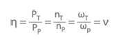
The pump impeller pushes the fluid inside the casing (usually low-viscosity oil) towards the runner, which causes the output shaft to rotate. Fluid couplings have no diffuser vanes between the pump (index P) and turbine (index T), unlike hydraulic torque converters As there is no diffuser being supported by the static casing, the fluid coupling's input (TP) and output torque (TT) are the same.
The power (PP = T · ωP) and (PT = T · ωT) are used to calculate the efficiency of the fluid coupling.
ν Speed ratio between turbine speed and pump speed ω Angular velocity
When the turbine speed (nT) is equal to zero, the fluid coupling has a very high driving torque. If the turbine speed is equal to the pump speed (nT = nP), the torque(T) equals zero. However, slip always occurs during power transmission, with the result that the turbine speed is lower than that of the pump.
See Fig. 2 Fluid coupling
Fig. 2 Fluid coupling: Characteristic curves for different filling volumes
Using an adjustable scoop tube to change the filling volume (V) makes it possible to control the slip (1-ν) and, in turn, the turbine speed.
In accordance with the hydrodynamic affinity laws, the turbine speed is also dependent on the pump speed. See Fig. 3 Fluid coupling
Fig. 3 Fluid coupling: Characteristic curves for different pump speeds
The wide variety of designs means that the characteristic curves can be matched to the requirements of the driving and the driven machine to the maximum possible extent. See Figs. 4 and 5 Fluid coupling
Fig. 4 Fluid coupling: Characteristic curves for different vane numbers z
Fig. 5 Fluid coupling: Characteristic curves of fluid couplings with a flattened section on the outside diameter and asymmetrical pump impeller and turbine runner
If combined with a gear unit (see gear drive) the fluid coupling is sometimes also referred to as a geared variable speed coupling. Mechanical separation of the input and output shafts dampens torque surges and vibrations. However, the disadvantage is that efficiency is sometimes significantly compromised (e.g. due to fluid coupling temperature rise) as a result of slip. This disadvantage can be mitigated by combining a fluid coupling with a hydraulic torque converter. In the lower speed and power range, the fluid coupling assumes responsibility for operation, whereas in the speed range of 80 to 100 % the input and output shafts are rigidly coupled. This means that the majority of the power can be transmitted without slip or losses, but allows a hydraulic torque converter to simultaneously continue to increase therotational speedand power (e.g. of the boiler feed pump) thanks to power splitting with a planetary gear unit (speed modulation gear).
Fluid mechanics is the science of liquid and gaseous media in motion (see Fluid). Within the context of hydrodynamics and partially aerodynamics, it investigates fluid flows which exhibit negligible changes in density (incompressible fluids) and, in the field of gas dynamics, gases where compressibility must be taken into account.
Fluid mechanics attempts on the one hand to set up and solve equations describing flow phenomena in theoretical terms, and on the other to present and interpret in a suitable form empirically established principles and relationships regarding certain fluid flow problems.
Depending on the number of coordinates required, a distinction can be drawn between one-, two- and three-dimensional flow phenomena which can be either steady (i.e. independent of time; see Steady flow) or transient (i.e. dependent on time; see Transient flow).
The theory described as "filament of flow" theory of one-dimensional flows deals with flows in a filament of flow limited on all sides by stream lines, and particularly with flows in pipes and closed ducts.
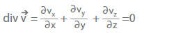
One fundamental equation in fluid mechanics is the continuity equation in differential form:
According to the filament of flow theory, the product of flow cross-section (A) and flow velocity (v) (averaged over the cross-section) remains constant along the filament of flow.
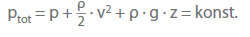
Furthermore, according to theBernoulli equation the total pressure (ptot), i.e. the sum of the static pressure (p), dynamic pressure ((ρ / 2) · v2) and elevation term (ρ · g · z), along a filament of flow in a frictionless flow is constant.
ρ Density of fluid handled g Acceleration due to gravity z Geodetic altitude
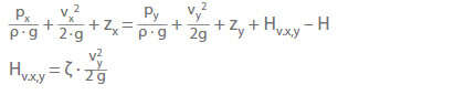
The extension of this equation to flows of viscous fluids between two arbitrarily selected cross-sections (Ax , Ay) of a pump system requires the head losses and pressure changes caused by a pump or a turbine between Ax and Ay to be taken into account:
g Acceleration due to gravity H Head of a pump (H > 0) or head of a turbine (H < 0) between the cross-sections Ax and Ay HLx,y Head loss along the flow path between the cross-sections from Ax to A y ζ Loss coefficient
If real two- and three-dimensional flows travel outside the boundary layer at a sufficient distance from solid walls and can therefore be considered as quasi-frictionless, they can generally be calculated by applying potential flowmethods..
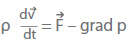
However, finding exact solutions for incompressible flows of viscous fluids by applying the equations of motion (Navier-Stokes equations) is only possible in a few simple cases.
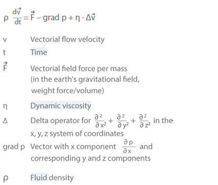
For a homogeneous Newtonian fluid (ρ, η = const.) this results in:
Given sufficiently high Reynolds numbers the general equations of motion for the thin boundary layers present in proximity to solid walls can be greatly simplified and solved by the various methods of the boundary layer theory. Based on the flow's microstructure, a distinction is made betweenlaminar and turbulent flow.
In the case of incompressible frictionless flow, the general equation of motion is simplified to the so-called Euler equation from which the Bernoulli equation is derived for steady flow.
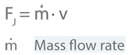
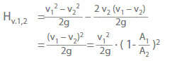
In centrifugal pump engineering, theprinciple of conservation of momentum or theorem of momentum plays an important role for incompressible steady flows. It represents the integral form of the Navier-Stokes equations. An example of application is the so-called Carnot shock loss in an incompressible flow through a diffuser with an abrupt increase of cross-section. See Fig. 1 Fluid mechanics
Fig. 1 Fluid mechanics: Carnot shock loss (application of the principle of conservation of momentum)
The diffuser has circular cross-sections. At the abrupt transition from the smaller cross-section (A1 = π · D12/ 4) to the larger cross-section (A2 = π · D22/ 4), a ring-shaped flow separation (a) develops as a result of the inertia of the flowing mass (wake or dead water). The flow only reattaches to the wall after a travel path (L) equal to at least 8 to 10 times the diameter D2.
The principle of conservation of momentum is to be applied to the outside forces acting in the direction of the flow velocity(v) on the fluid enclosed in the defined space (depicted in the illustration by the dash-dotted lines). The momentum forces (FJ) should constantly be directed toward the enclosed fluid.
Other forces involved are the pressure (Fp) and friction (Fv) forces.
p Static pressure Ap Cross-section area on which the static pressure acts Av Internal pipe wall on which the wall shear stress acts τ Wall shear stress (wall friction)
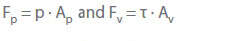
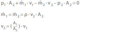
The wake or dead water flow (see Boundary layer)at the pipe wall causes the friction forces (Fv) to be negligible. Therefore, according to the principle of conservation of momentum, the equilibrium of forces in the direction of the flow velocity (v) (positive direction) can be expressed as:
According to the principle of conservation of momentum, the difference in static pressure becomes:
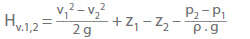
According to the Bernoulli equation, the following applies to a filament of flow, taking into account the pressure loss (HL1,2):
If (p2 – p1) is now inserted as derived from the principle of conservation of momentum, the following applies with z1 = z2:
Because of the similarity between the above equation derived from the principle of conservation of momentum and the equation for the loss of energy in a straight-line inelastic impact of two bodies, the head loss obtained from the last-mentioned equation has been named Carnot shock loss in fluid mechanics.
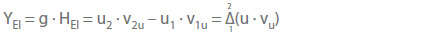
A further important application of the principle of conservation of momentum leads to the so-called fundamental equation of turbomachinery: If an impeller's vanes (see Vane) are subdivided into impeller elements, where one element (subscript El) lies between two adjoining flow surfaces (see Flow line) of the relative flow in the impeller (seeRelative velocity) the specific energy transmitted by the vanes of the impeller element (YEl) is:
u1 Circumferential speed of impeller at inlet (relating to the characteristic stream line of the impeller element) u2 Circumferential speed of the impeller at outlet (relating to the same stream line) v1u Tangential component of absolute velocity (v) at impeller inlet (relating to the stream line pertaining to u1 and u2) v2u Tangential component of absolute velocity (v) at impeller outlet (relating to the same stream line)
The fundamental equation of turbomachinery applies to any type of impeller or runner in centrifugal pumps and turbines.
The equation is independent of the density of the fluid handled and can also be applied to applications where the fluid's density changes during its passage through the impeller, e.g. to gaseous fluids, steam and vapours.
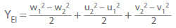
Another method for expressing an impeller's specific energy is:
w Relative velocity u Circumferential speed v Absolute velocity
In this equation the first two terms can be interpreted as the difference in static pressure energy across the impeller. The energy difference resulting from the components of absolute velocity is only available as velocity energy and therefore must be converted into pressure energy in the diffuser elements or diffusers.
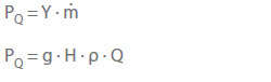
The specific energy generated by the entire impeller (Y) is established by averaging the mass flow rate for all impeller elements. The following relationship exists between the specific energy of the impeller (Y) and the pump power output (PQ):
Q Flow rate through the impeller ρ Density of fluid handled g Acceleration due to gravity H Head
ṁ Mass flow through the impeller
If this is applied to the impeller element, the specific energy of the impeller element (PEl) is:
Following the addition of the power losses, the centrifugal pump's input power (P) is:
The foot valve is a lift check valve, which is usually installed together with suction strainers in the suction line. It prevents the suction line from running empty after the pump is stopped (also see Valve). The foot valve should be installed in such a way that an appropriate distance between the valve, the pump sump floor and the lowest suction-side water level is maintained. A type often used is a cup valve as it features favourable flow characteristics (see Head losses). See Fig. 1 Foot valve
Force is a vectorial (directional) magnitude from mechanics and is the cause of the acceleration or deformation of a body. The SI unit of force is N (Newton), which is the effective force which imparts an acceleration of 1 m/s² to a body with a massof 1 kg.
The term "formation of air pockets" describes the accumulation of air bubbles in certain areas inside pipes or centrifugal pumps which can seriously impair pump operation. They occur due to gas (mostly air) contained in the fluid handled in dissolved or undissolved (bubble) state (see Gas content of fluid handled).
To avoid the formation of air pockets, suction lift lines must be laid with a rising slope towards the pump. If possible, each pump should have its own individual suction line so that no air can penetrate the suction line via a non-operating pump when only one pump is running. Shut-off gate valves (see Valve) in suction lift lines should be fitted with their stem in a horizontal position.
Eccentric reducers and branch fittings should be used in horizontal suction lift lines. See Figs. 5, 6 Fitting
Valve stems' gland packings should preferably be connected to a water supply under pressure. For long discharge lines incorporating rising and falling stretches of piping, each high point must be provided with an automatic vent valve.
In water management the process of fouling describes the deposition of particles on wetted surfaces due to gravity. If water supply networks employ cast iron pipes without cement mortar lining, fouling may develop on all internal pipe surfaces. This type of fouling is created by a calcium carbonate/iron mixture. Under certain conditions, fouling in water pipes may grow to such an extent that only very small quantities of water can pass through the pipe.
The term free passage refers to a free, unrestricted impeller passage and defines the max. permissible diameter solid substances (fruit, vegetables, etc. in the food industry, for example) may have to pass the impeller without causing clogging. It is specified in mm as a spherical diameter or with rectangular dimensions in the characteristic curves of free-flow, channel or single-vane impellers (also see Impeller).
The free-flow impeller is a radial impeller, which has a large free passage for solids contained in the fluid handled and is the least susceptible to clogging Sewage pumps are fitted with these impeller types. See Fig. 1 Free-flow impeller, Fig. 3 Waste water pump and Fig. 3 Sewage pump
Frequency is the characteristic magnitude of recurring events during a periodic phenomenon such as a vibration. It is defined as the reciprocal of the cycle time. The unit of frequency is s = 1 Hz (Hertz).
In electrical engineering, the mains frequency is the number of oscillations of the alternating current and of the alternating voltage per second. In Europe, most supply networks have a frequency of 50 Hz, with a very few examples of 42 Hz as in Italy. In addition, a mains frequency of 60 Hz is used in North America and other parts of the world where the supply of energy has been dominated by American firms. This frequency is also often found on board ships.
In power engineering, apart from the usual frequency of 50 Hz, a frequency of 16 2/3 Hz is used in certain instances (e.g. German Federal Railways).
A frequency inverter is an electronic device that receives three-phase or alternating current and changes the output voltage in amplitude and frequency. This is then used to improve the run-up and speed behaviour of three-phase motors (also see Starting method). Frequency inverters also control the rotational speed of single-phase asynchronous motors, whereby the inverter energises the second phase previously generated by the capacitor.
Core components of the frequency inverter include a rectifier that feeds a direct-current or direct-voltage link and an inverter powered by this link. The inverter generates a voltage whose mean waveshape corresponds to the sinusoidal voltage of the required frequency and amplitude. See Fig. 1 Frequency inverter
Fig. 1 Frequency inverter: Simplified schematic
Three-phase motors operated using a frequency inverter can infinitely vary their rotational speeds from zero up to their nominal speed without experiencing a drop in torque. Since frequency inverters produce substantial electrical interference along the motor supply cable, they must frequently be shielded (see Shielding). A sine filter between the frequency inverter and the motor can also suppress interference.
The frequency of starts for pumps refers to the number of times the electric motors that power them start up per hour. The permissible frequency of starts depends on the motors used and their power, rotational speed, and type. See Fig. 1 Frequency of starts
Fig. 1 Frequency of starts: Permissible number of electric motor starts per hour
Start-ups lead to the build-up of heat in electric motors and flexible couplings and cause the contactors to wear prematurely, which limits the permissible frequency of starts. Exact information about the number of hourly start-ups permitted should be obtained from the motor's supplier with respect to operating conditions.
The FROUDE number is a dimensionless physical characteristic coefficient used in flow analyses which can be interpreted as the ratio of inertia force to gravity force (see also Similarity conditions, Affinity laws). It is of major importance in naval architecture.
Functional earthing is a type of earthing, that forms a functional part of an electrical installation and is vital to ensuring its trouble-free operation. Interference current can be discharged, testing adapters earthed, and common reference potentials defined for electrical devices and equipment.
The fuse is a protective device that interrupts a circuit when a specific electric current is applied for a defined period of time. Examples include the melting fuse and the miniature circuit breaker. See Fig. 1 Fuse
Fig. 1 Fuse: Circuit with fuse protection
When a melting fuse is triggered, the circuit is interrupted by the thermal effect of the current, which also destroys the fuse. This fuse can then no longer be used.
A standard variant is the device and micro fuse, which is also referred to as the G-fuse or glass tube fuse and comprises a small glass or ceramic tube with a metal cap on both ends. A fuse element is integrated in the tube.
Key values such as the nominal current, maximum voltage, and tripping characteristic of the G-fuse are indicated on the metal caps. The tripping characteristic indicates how quickly the fuse responds to overcurrent, whereby a distinction is made between FF (fast fuse) (< 20 ms), F, M, T, and TT (super time lag) (> 300 ms).

")


")
")


; basic principle of a U-tube pressure gauge")
")
; lime stone scrubbing")
 lining")


")