Mixed flow pump
A mixed flow pump is a centrifugal pump with a mixed flow impeller. The specific speeds (ns) lie between 35 and 80 rpm for low-speed mixed flow pumps, and between 80 and 160 rpm for higher-speed mixed flow pumps (in special cases even higher). Mixed flow pumps cover the transition range between radial flow pumps and axial flow pumps (e.g. propeller pumps).
The impellers of mixed flow pumps with a low specific speed are combined with an annular or volute casing; those of mixed flow pumps with a higher specific speed are combined with a diffuser and a tubular casing.
See Fig. 1 Mixed flow pump

Fig. 1 Mixed flow pump: Volute casing pump with open mixed flow impeller and vortex volute
The optimum specific speed range for tubular casing mixed flow pumps with regard to construction costs and efficiency is not clearly defined. However, from approximately 130 rpm upwards, the tangential component of the absolute velocity at the impeller outlet becomes so small in comparison with the flow velocity at the pump suction nozzle that the end cross-sections of the volute or annular casing required to convey the flow (see Flow rate) would become disproportionately large. In such cases the mixed flow pumps would have to be designed with an excessively large radial casing, which would possibly still be viable if made of concrete but very expensive if made of cast iron or steel. See Fig. 6 Cooling water pump
For this reason, mixed flow pumps with higher specific speeds are usually designed with an axial tubular casing and an "onion type" or axial flow diffuser through which the fluid flows towards the discharge elbow and the pump discharge nozzle.
The range of heads of mixed flow pumps with tubular casing complements that of the propeller pump at the top end of the head range. As the circumferential velocity of a mixed flow impeller is restricted to 25 to 30 m/s to prevent cavitation (see Suction characteristics) the mixed flow pump can only exceed its maximum head of H = 60 m if it is designed as a multistage pump. In practice, the number of stages is limited to two or three.
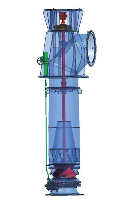
As the impeller geometry of mixed flow pumps, unlike that of propeller pumps, does not allow closed-loop control by means of impeller blade pitch control, pre-swirl control is recommended. Pre-swirl control is effected by means of a cardan shaft connected to a rod structure leading above floor level outside the tubular casing. See Fig. 2 Mixed flow pump and Fig. 10 Cooling water pump

Fig. 2 Mixed flow pump: Tubular casing pump with pre-swirl control equipment
In the case of multistage mixed flow pumps with tubular casing, pre-swirl control devices can be applied upstream of each individual impeller at every stage. In many cases, however, the overall control effect of a single pre-swirl control device fitted upstream of the first stage is sufficient.
If the fluid handled is clean and the heads are no higher than 15 m, it is unnecessary to fit a front shroud on mixed flow impellers (see Open impeller). For higher heads, closed impellers are recommended in order to reduce clearance gap losses (see Clearance gap width).
