Country, region and language selection

International websites

Europe

Americas / Oceania

Africa and Middle East

Asia / Pacific

Hydraulic model testing: Air intake in pumping systems
9 min read

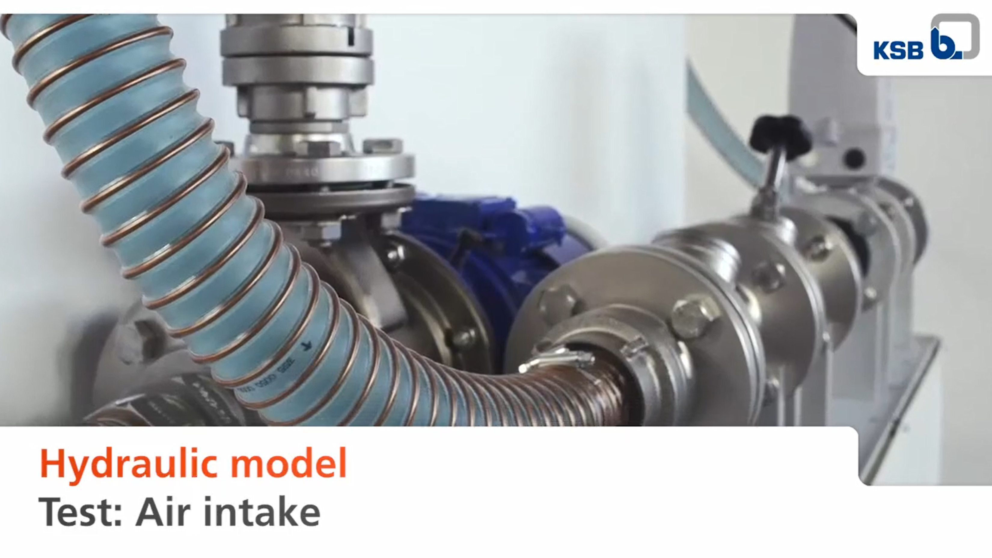
"Air intake" hydraulic model testing: How to prevent gas bubbles in pumping systems.

A centrifugal pump should draw in as little undissolved gas (e.g. air) as possible. Gas bubbles could collect in its centrifugal force field, in the impeller or casing, and interfere with the flow. In comprehensive model testing, KSB investigated the options of preventing or reducing gas bubbles in pumping systems. Read on to find out more.

A centrifugal pump should draw in as little undissolved gas (e.g. air) as possible. Gas bubbles could collect in its centrifugal force field, in the impeller or casing, and interfere with the flow. In comprehensive model testing, KSB investigated the options of preventing or reducing gas bubbles in pumping systems. Read on to find out more.

KSB has started comprehensive model testing to investigate options of reducing air intake.

Applicable regulations and recommendations specify that the inflow into the suction chamber of a pumping system is to be designed in such a way that air is prevented from entering the pumps. For a good reason: The intake of air or other undissolved gases in liquids to be transported can seriously interfere with the flow in a pump. This may alter the characteristic curve and impact on the operating behaviour. To investigate the options of reducing air intake, KSB conducted some comprehensive hydraulic model tests.

The test model comprised a tank and an inlet line located above the water level on the left-hand side. The height of the inlet and its distance to the pump were adjustable. In addition, the test model had a pipe leading to the pump and the option of fitting a deflector and a balcony-like structure. Relevant factors for the model test were the water level in the tank, the outlet velocity and the height of fall of water. 

The first part of the test was carried out without a deflector and at a low height of fall.At a flow rate of approx. 4 m³/h the air entered the water and was swirled. Larger gas bubbles quickly rose to the surface; smaller gas bubbles were transported in the direction of the pump's inlet pipe. The flow rate was then increased to approx. 8 m3/h. This resulted in a larger amount of air intake in the direction of the pump's inlet pipe in the model test. A larger number of larger air bubbles reached the pump's inlet pipe. When the flow rate was increased to 12 m³/h, the air intake affected the entire right-hand side of the tank. A large quantity of gas bubbles entered the pump's inlet pipe. 

The second part of the model test was carried out without a deflector at a large height of fall, at a flow rate of approx. 4 m³/h. The jet penetration depth was large in this part of the test. The air was blown deeply into the water, swirled and moved in the direction of the pump's inlet pipe. Medium-sized and small bubbles entered the pump's inlet pipe. The flow rate was then increased to approx. 8 m³/h. This demonstrated: The larger the height of fall and the outlet velocity, the larger the air intake. This resulted in larger gas bubbles also entering the pump's inlet pipe. When the flow rate was increased to approx. 12 m³/h, the jet hit the far right of the tank, near the pump's inlet pipe, causing swirls at the right-hand wall of the tank. This did not further increase the penetration depth.

Preventing air ingress by using a deflector and balcony

The third part of the test was conducted at a low height of fall and with a deflector that broke the water jet before it flowed into the tank. The model test was started at a flow rate of approx. 4 m³/h. The air intake was swirled deeply into the water and largely held back by the deflector. Gas bubbles quickly rose to the surface behind the deflector. Only a few gas bubbles reached the pump's inlet pipe on the right-hand side of the tank. 

The flow rate was then increased to approx. 8 m³/h. Here, a large quantity of air bubbles (almost half) were held back by the deflector or rose directly to the surface on the rear of the deflector. In this part of the test, only a few small gas bubbles reached the pump's inlet pipe. When the flow rate was increased to approx. 12 m³/h, the air intake increased and was swirled by the lower end of the deflector. Small and medium-sized air bubbles were transported in the direction of the outlet opening and reached the pump.

For the fourth part of the test, the height of fall was increased. The initial flow rate was approx. 4 m³/h. The air intake was swirled deeply into the water but largely held back by the deflector. Only a very small number of the tiniest of gas bubbles reached the pump. The flow rate was then increased to approx. 8 m³/h. The water jet hit the deflector via the water surface. The water jet was deflected vertically at the deflector and swirled together with the air intake mainly in the left-hand part of the tank. Only very small quantities of small gas bubbles reached the pump's inlet pipe. When the flow rate was increased to approx. 12 m³/h, the water jet was already deflected by the deflector above the water level. The number of smaller air bubbles that reached the pump's inlet pipe increased in this case. 

The fifth part of model testing was carried out with a deflector and a balcony, at a low height of fall. The first model test was carried out at a flow rate of approx. 4 m³/h. It showed that the air bubbles were immediately swirled back by the balcony on the left-hand side of the deflector. The air bubbles did not reach the pump's inlet pipe. When the flow rate was increased to approx. 8 m3/h, the result was the same: The larger amount of air intake was also held back by the balcony and remained in the left-hand tank half. This hardly changed even when the flow rate was increased to approx. 12 m³/h, resulting in more air intake. Only a very small amount of air intake reached the pump. 

The sixth and last part of model testing was conducted with a deflector and a balcony at a large height of fall. The flow rate in the first part of the model test was approx. 4 m³/h. Here, the air bubbles entered the water deeply but were held back by the deflector and balcony on the left-hand side of the tank. When the flow rate was increased to approx. 8 m³/h, most of the air bubbles were also held back by the balcony and swirled in the left-hand part of the tank. Only very small amounts of smaller air bubbles reached the right-hand side of the tank with the pump's inlet pipe. When the flow rate was increased to approx. 12 m³/h, the swirls became stronger because of the deflected water jet. At this flow rate, too, a large amount of air intake remained mainly on the left-hand side of the tank thanks to the balcony.


Conclusion of the "air intake" model testing

Air intake can have a negative impact on the smooth running and output of a pump if the pump draws in air. When planning a pumping system, the intake of air or other gases by the fluid handled should definitely be prevented or minimised. If a difference in height between the pipe invert and the minimum water level cannot be avoided, the use of deflectors and balcony-like structures can markedly reduce air intake, as demonstrated by KSB's "air intake" hydraulic model testing. 

Model testing by KSB: Thinking small, building big! 

In general, KSB conducts model tests for an object or procedure whenever the measurement of original conditions is not technically or economically feasible. Experimental investigations enable KSB to find new potentials for increasing efficiency in pumping systems.

The hydraulic "air intake" model test was only one of many model tests carried out by KSB. Expand your specialist knowledge with the results of some of our other hydraulic model tests on topics such as gas pockets, benching angle or solids transport.

Good to know: When planning, performing and evaluating all model tests and transferring the results to the original-size machine and/or the original operating conditions, the affinity laws are observed and applied. Apart from maintaining geometric similarity, this involves considering changes in length due to elastic and thermal deformations, converting test results on the basis of affinity laws, observing fluid properties, and much more. 

In other words, everything that allows a model test to optimise the daily operation of a pumping system in real life.

Do you have any questions? Please contact us. We look forward to hearing from you.

Suitable products

Amarex KRT

Amarex KRT

Horizontal or vertical single-stage submersible motor pump in close-coupled design, with various next-generation impeller types, for wet or dry installation, stationary or transportable version, with energy-saving motor and models for use in potentially explosive atmospheres.

Etanorm

Etanorm

Horizontal volute casing pump, single-stage, with ratings and main dimensions to EN 733, long-coupled, back pull-out design, with replaceable shaft sleeves / shaft protecting sleeves and casing wear rings, with motor-mounted variable speed system. With KSB SuPremE, a magnetless synchronous reluctance motor (exception: motor sizes 0.55 kW / 0.75 kW with 1500 rpm are designed with permanent magnets) of efficiency class IE4/IE5 to IEC TS 60034-30-2:2016, for operation on a KSB PumpDrive 2 or KSB PumpDrive 2 Eco variable speed system without rotor position sensors. Motor mounting points in accordance with EN 50347, envelope dimensions in accordance with DIN V 42673 (07-2011). ATEX-compliant version available.

Multitec

Multitec

Multistage horizontal or vertical centrifugal pump in ring-section design, long-coupled or close-coupled, with axial or radial suction nozzle, cast radial impellers and motor-mounted variable speed system. ATEX-compliant version available.

Stay up to date with the KSB Newsletter.

Want to make sure you never miss the latest news? With the KSB Newsletter you will receive information on our products and solutions, current promotions and events as well as fascinating insights into the world of KSB.

Don’t hesitate to contact us.

Would you like further information on KSB? Or have you got any questions surrounding our pumps, valves, services and spare parts? Just contact us. We would love to talk to you.